
|
Settling is understood to be the sinking of solids in liquids (or gases) under the influence of gravity. That means that particles of the same mass are subject to the same settling conditions irrespective of their size (diameter, volume). Merely for particles of the same density, settling has a classification (screening) effect [HDD-263]. In solids control in HDD, the settling takes place on purpose in settling tanks (sand trap), hydrocyclones and … |

|
In all cases where liquid drilling fluid is used, it is necessary to utilize a separation plant (also called recycling plant) for cleaning and reclaiming the drilling fluid and dewatering the spoil in order to make it ready for disposal. In drilling technology, this process is described with the term “solids control”. An optimally working solids control is a fundamental prerequisite for the technical and economic success of an HDD project and furthermore … |
|
Important aspects that also determine the cost effectiveness of a hydraulic conveying installation are the type and scope of the separation that is required and the preparation of the pumped solids-fluid mixture. The purpose of separation is the removal of the solid components from the fluid, on the one hand, to return the drilling fluid medium again to the conveying circuit and, on the other hand, to make the separated solids (spoil) fit for disposal. … |

|
HDD methods require the use of drilling fluids. Drilling fluids refer to the controlled circulation of fluids in the borehole or in the conveying circuit and include fluids, gasses or a mixture of the two. Drilling fluids with gas play only a minor role in the trenchless installation of pipes and cables - only being applied in Dry Horizontal Directional Drilling (Dry HDD) (see (Dry Horizontal Directional Drilling)). This is why, in the following, … |
|
(Image: Down-hole hammer drill rig)Dry Horizontal Directional drilling, also referred to as Dry (Guided) Boring or Dry Directional Drilling(r) (DDD®) [HDD-272] [HDD-273] [HDD-274], is based on the principle of the down-hole hammer drill rig. This is an percussiverotating frame-mounted drill rig, in which the impact mechanism (pneumatic down-hole hammer) is situated right behind the drilling tool in the drill string and is inserted into the borehole. … |

|
The method of operation involves the same working steps as for Horizontal Directional Drilling: -
pilot boring,
-
reaming(s),
-
pulling-in process.
These working steps are described in depth in (Method of operation and sequence) and are to be transferred to this technique in a corresponding way. |

|
The equipment of the Dry Horizontal Directional Drilling methods is virtually identical with that needed for Horizontal Directional Drilling described in (Equipment). The differences solely result from the drilling fluid and the use of the pneumatic downhole hammer as an impact mechanism. The use of air instead of drilling fluid requires the following additional equipment: -
air compressor,
-
drilling fluid tank for adding water or foaming agents to …
|
|
Dry Horizontal Directional Drilling methods are predominantly used for the installation of casing and host pipes for telecommunication cables [HDD-280] [HDD-281] [HDD-282] [HDD-283], but also find use for water and gas pipes [HDD-284] [HDD-285] [HDD-286] as well as for pressure sewers. Often only pilot boring is carried out with this method. In suitable loose soils (dry, non-cohesive, loose) normally soil displacement and soil extraction are combined. … |

|
Based on the HDD methods described above, efforts
concerning constructional and/or mechanical advances
were made in the past years. In the following, two
examples are given, one of which has not progressed
beyond the prototype stage. |
|
The GRUNDOPIT with “hammer bore head” [HDD-23] (Figure 209a, b and c) can be counted among the rotatingimpact Dry Horizontal Directional Drilling methods. It possesses a special rock cutting head with a cut-off wall-type pre-separator (Figure 209 a), which is activated via an impact cylinder driven by compressed air and which can be used with the drill rig variants GRUNDOPIT Power and GRUNDOPIT Shaft (see (Grundopit method)) (cf. Table 35) [HDD-38] [… |
|
The SYSTEM ONE method [HDD-291], which until now has only been employed as a prototype, uses drilling fluid as well as air depending on the subsoil situation. In the pilot boring, the method always works as a direct HDD, which means that the loosened spoil is transported through the annular space between drill rods and borehole wall. In the reaming stage, the method can work as direct as well as indirect HDD. (Image: SYSTEM ONE method - design of the … |

|
Based on the HDD methods described above, efforts
concerning constructional and/or mechanical advances
were made in the past years. In the following, two
examples are given, one of which has not progressed
beyond the prototype stage. |
|
(Image: Down-hole hammer drill rig)Dry Horizontal Directional drilling, also referred to as Dry (Guided) Boring or Dry Directional Drilling(r) (DDD®) [HDD-272] [HDD-273] [HDD-274], is based on the principle of the down-hole hammer drill rig. This is an percussiverotating frame-mounted drill rig, in which the impact mechanism (pneumatic down-hole hammer) is situated right behind the drilling tool in the drill string and is inserted into the borehole. … |

|
According to DIN EN 14457 [HDD-294] and/or DIN EN 805 [HDD-296], a pipe is a “component of uniform bore, normally straight in axis, having e.g. socket, spigot or flanged ends.” The pipes that are pulled into the usually expanded borehole when using HDD (pulling-in process, see (Method of operation and sequence)), can be classified among the category of jacking pipes. In the following discussion, jacking pipes will be understood to be prefabricated … |

|
(Image: Possible mechanical strain of the pipe coating while pulling-in)Even today, there are neither national nor European standards that define general requirements of jacking pipes irrespective of the type of pipe. A first attempt at this is the EN 12889 [HDD-9] that, in an extremely restricted form in Section 5.2 “Pipes and joints” for drains and sewers, is formulated as follows: “Installation shall not commence before the following criteria have … |
|
EN 805 [HDD-296] refers to internal diameter (ID), also called inside diameter, as the “mean internal diameter of the pipe barrel at any cross section”. EN 805 [HDD-296] defines the external diameter (OD), also called outside diameter, as the “mean external diameter of the pipe barrel at any cross section. For pipes with externally profiled barrels, the external diameter is taken as the maximum diameter when viewed in cross section.” Standards using … |
|
In EN 14457 [HDD-294], pipe length is defined as the “length of the internal pipe barrel”. For HDD, pipes can be supplied in continuous lengths (due to transport reasons because of the StVZO [HDD-298] up to maximally 12.0 m length, in exceptional cases also up to 18.0 m length), or as bundled coils and/or drums (up to maximally 100 m length) with reference to the material (flexible or rigid pipes). |

|
Meeting the tolerance on dimension or tolerances of the jacking pipes used for HDD is of special importance for creating a high-quality pipe connection as well as for the transfer of the pullback forces when pulling-in. Furthermore, the functionality of the later pipeline is influenced regarding its leak tightness, operational safety and the flow conditions, for example. |
|
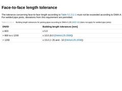
The tolerance concerning face-to-face length according to Table 49 must not be exceeded according to DWA-A 125 [HDD-10]. For welded pipe joints, deviations from this requirement are permitted. (Table: Table 49: Building length tolerances for jacking pipes according to DWA-A 125) |

|
(Image: Measuring the rectangularity of the end faces of the pipe)Deviation from the rectangularity of the pipe’s end faces is defined as the sum of the deviation of the pipe’s total end face from rectangularity and the deviation from the rectangularity (opposite skin lines) within the pipe wall thickness spipe. The rectangularity of the end faces at each pipe end is defined as Δa = max a - min a with reference to Figure 213. According to DWA-A 125 [… |

|
Irrespective of the design length of the jacking pipe, according to DWA-A 125 [HDD-10], the skin line must deviate from the straight line by less than the value given in Table 51. For steel jacking pipe 1.5 mm per m design length must not be exceeded. The deviation is to be measured over the total length of the outside pipe barrel minus possible joint profiles and 50 mm for side inlets. In this regard, [HDD-40] asks for a value of 0.9 mm per m design … |

|
According to DWA-A 125 [HDD-10], the tolerances for the maximum external pipe diameter are collected in Table 52. Concerning this matter for HDD, [HDD-40] specifies that for steel pipes the maximum difference between the smallest and the largest external diameter must not exceed 1% or 6 mm, depending on which value is the greatest. For PE, PVC and ductile cast iron, similar tolerances apply. (Table: Table 52: Permissible deviation from the max. outside … |
|
Meeting the tolerance on dimension or tolerances of the jacking pipes used for HDD is of special importance for creating a high-quality pipe connection as well as for the transfer of the pullback forces when pulling-in. Furthermore, the functionality of the later pipeline is influenced regarding its leak tightness, operational safety and the flow conditions, for example. |
|
The permissible pullback forces for pulling-in the pipes depend, among other things, on the following parameters: -
pipe manufacturer,
-
nominal pipe size,
-
wall thickness,
-
pipe joint,
-
construction site conditions,
-
pulling-in length,
-
borehole condition,
-
load bearing capacity of the soil,
-
neighbouring infrastructures,
-
drill rig used.
Detailed information regarding the permissible tensile forces with reference to the pipe material are given in (… |
|
According to EN 14457 [HDD-294], a pipe joint, or also simply called joint, is defined as the “connection between the adjacent ends of two components including the means of sealing and pressure transfer ring, (during installation) if applicable.” The pipe joint must ensure that the following criteria are met: -
tightness against internal and external pressure
-
transferral of longitudinal forces (here: pullback forces) whilst ensuring lateral stability,
|