
|
The following approach has proven to be useful in seeking information: -
Enquiries at public utility companies, civil engineering offices or drainage departments/companies, telecommunication companies, energy-, gas- and water suppliers and other utility and waste removal services.
-
If there are no plans available, ask for a written confirmation that explicitly states the absence of third party pipes in the area of the lines and manholes under rehabilitation.
|

|
|
|
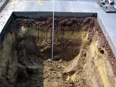
This module teaches the basics of geotechnical investigations for civil engineering purposes. The described subsoil investigation by indirect (e.g., drilling methods) and direct exploration methods (e.g., dynamic sounding) form the basis for an understanding of a civil engineering description and evaluation of soil and rock. After completing this module, you will have a sound knowledge of: - The objective of a geotechnical investigation;
- The purpose of structural and subsoil investigation by means of excavations;
- Differentiation between direct and indirect excavation methods, such as drilling methods and indirect excavation methods, such as dynamic sounding.
|

|
Aug 31, 2023
News
Melissa Bailey
System to provide renewable power, reduce wastewater utility costs, and cut greenhouse gas emissions for East County Advanced Water Purification facility.
|

|
The documentation of damages, defects, other peculiarities (findings) in sewers and pipes within the scope of CCTV inspection is not possible without a uniform nomenclature. In Europe, EN 13508 Part 2: "Coding system for visual inspection" provides the normative basis for documenting and describing various findings, which later serve the engineer as a basis for assessment.
This module provides the basic knowledge required for the structure and application of the coding system. After completing this module, you will have a sound knowledge of: - coding system according to EN 13508-2;
- differentiation between basic information and findings;
- differences in the coding system between sewers and manholes;
- codes for route finding, tightness indication, location on the circumference and
- procedure of inspection in an object.
Duration:
2,5 h |

|
|

|
European coding systems define the term defect as „a structural, environmental or hydraulic condition that causes or is expected to cause an unacceptable impairment of functionality with regard to use. “ [ATVM143-1:2004]. The following explanations refer primarily to structural defects, hereinafter also referred to as damage. These damages can also be of importance when assessing the hydraulic performance and the impact on the environment, but also … |
|
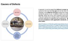
(Image: Diagram - Causes of Defects) In general, it can be stated that defects in sewer systems are caused on the one hand by age and on the other hand by changes in the different stresses acting from outside or inside during the period of use. In addition, there is so-called initial damage, which can occur over a period of up to several years. They are mainly due to design and/or material defects and/or incorrect selection of materials and components - |
|
Important: Knowledge of the defects, their manifestations, causes and consequences is one of the most important prerequisites for the optimal planning and design of integral solutions to meet the performance requirements - and here in particular for the selection of suitable procedures for the structural solution. The following explanations refer primarily to structural defects, hereinafter also referred to as damage. These damages … |

|
A coding system consists of codes for basic information and individual observations, whereby the codes for individual observations within the sewers and drains are to be binding. Observations are understood to mean defects and condition characteristics, and header information refers to a pipeline as a whole. It is recommended to adopt the binding codes of EN 13508-2 as completely as possible. In justified individual cases, restrictions may be proposed. |

|
|

|
Header information according to [EN13508-2:2011]: -
relate to the pipeline as a whole,
-
describe the conditions of the inspection as well as the pipeline and possible changes in it,
-
include project data, and
-
serve to clearly identify the object for allocation to the sewer inventory and to describe the inspection conditions.
(Image: Inspection report - marking Header Information) |

|
(Image: Sewer Section Identification) The Header information is supposed to be entered at the start of the inspection. According to [EN13508-2:2011], the following information shall be recorded: (a) The pipeline (length) identification occurs by: -
pipeline reference and/or the two node references.
-
Alternatively, where the pipeline length is a lateral connected to another pipeline without a chamber, the pipeline may be identified the following way:…
|

|
(b) The direction of the inspection -
Inspection and documentation direction are based on the client's specifications
(c) A textual description of the location -
The name of the local authority, name of the district, name of a street, or name of a square.
(d) The coding system -
The coding system must be specified and clearly designated, e.g., according to Code of Practice [EN13508-2:2011], [DWAM149-2:2013]
(e) The longitudinal reference point (if recording … |

|
(f) The Method of Inspection -
The inspection method must be specified. For example:
-
TV sewer cameras
-
manhole inspection systems based on video camera technology
-
manhole inspection systems based on digital photo technology
(g) Further Basic Information -
date of inspection
-
whether the drain or sewer was pre-cleaned
-
any other information required by the employing authority
|

|
Further binding header information can be: -
name of the client and contractor
-
name of the equipment operator
-
camera system
-
purpose and time of inspection
-
discharge control yes/no
-
shape and dimensions (with indication of data origin, i.e., measured, estimated, taken from a plan)
-
material
-
lining details
-
standard pipe length
-
type of wastewater
Important: Further header information can be requested by the client. A height measurement … |

|
Master Data -
The client must provide the master data necessary for the visual inspection and make specifications for the recording of changes.
-
Master data must be checked by the inspector during the inspection.
-
Where any information specified in the header changes during the inspection, the revised information shall be entered using the relevant code as described below (table).
|

|
|

|
Example 3: Cancelling the visual inspection and continuing the inspection from the opposite direction, the opposite side (of the obstacle) is reached. 1. Data set: BCDXP - BBAA - BDCYY 2. Data set: BCDXP - BBAA - BDCYC (Image: Control code - visual inspection image 2) |