
|
In accordance with EN 13508-2 [ [EN13508-2:2011]], the main code “Other obstacles” captures “objects in the catch basin”. This code, analogously to types of obstacles occurring in manholes and inspection chambers, should only be used in the case that the main codes for “Attached deposits” ( (Attached deposits (SBB))) and “Ingress of soil” ( (Ingress of soil material (SBD))) cannot be applied. The type of obstacle is characterised by a description … |

|
In accordance with EN 13508-2 [ [EN13508-2:2011]], the main code “Infiltration” is defined as the “ingress of water through the wall of the catch basin, connections or defects in the wall”. Infiltration is a so-called secondary form of defect that is caused by a primary form of defect, i.e. leakages, and describes the infiltration of groundwater in most of the cases. This type of defect is characterised by the intensity of water ingress and the area … |

|
In accordance with EN 13805-2 [ [EN13508-2:2011]], in the case of catch basins, “Exfiltration”, just as the main code DBG for manholes and inspection chambers suggests ( (Exfiltration (DBG))), is defined as a visible leakage of flow out of the catch basin without any further characterisation or quantification of defect. For catch basins with a sump (SS), an in situ water level right below the bottom edge of the outlet can be considered an indication … |

|
In accordance with EN 13508-2 [ [EN13508-2:2011]], the main code “Vermin”, just as for manholes and inspection chambers, is only applied in the case of “actually observed vermin”. This type of defect is characterised subject to the species and its localisation: -
Species
-
Rat (additional code specification A)
-
Cockroach (additional code specification B)
-
Other (additional code specification Z; further remarks are to be recorded)
-
Localisation of vermin
|
|
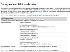
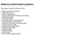
In addition to the main codes used to describe the structure and operation of catch basins, “Survey codes” and so-called “Additional codes” are also defined in accordance with EN 13508-2 [ [EN13508-2:2011]]. These two code groups do not serve a damage description purpose, but are simply used for a further description of the inspected catch basins. Subsequently, they will not be described in detail, but illustrated in the form of a table. (Table: Summary … |
|
|

|
As shown in the preceding sections, drain and sewer systems are prone to a variety of types of damage due to different causes. The subsequently described damage analyses are done separately for drains and sewers as well as manholes, inspection chambers and catch basins. |

|
Ever since leaking sewer systems came into public focus in the Federal Republic of Germany, finding answers to questions about the actual damage potential and the most favourable point in time for damage repair (rehabilitation) has been of great relevance from an economic, ecological and legal point of view. For that purpose, the DWA has started nationwide surveys among network operators in 1984/85 [ [Kedin87]]. The latest survey from 2009 brought … |
|
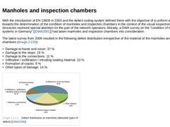
With the introduction of EN 13805 in 2003 and the defect coding system defined there with the objective of a uniform approach towards the determination of the condition of manholes and inspection chambers in the context of the visual inspection, these structures received special attention on the part of the network operators. Already, a DWA survey on the “condition of the sewer systems in Germany” [ [DWA2001]] had taken manholes and inspection chambers … |
|
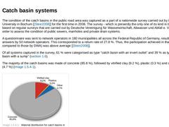
The condition of the catch basins in the public road area was captured as a part of a nationwide survey carried out by Ruhr University in Bochum [ [Stein2008]] for the first time in 2006. The survey - which is presently the only one of its kind in that form - was based on regular surveys that are carried out by Deutsche Vereinigung für Wasserwirtschaft, Abwasser und Abfall e. V. (DWA) in order to assess the condition of public sewers, manholes and … |
|
|

|
Sewer systems are either permanently or temporarily subject to different physical, chemical, biochemical and biological forms of stress. The second volume of the 2nd edition of "Rehabilitation and Maintenenance of Drains and Sewers" deals with the various types of defects and damages threatening drains, sewers, manholes and catch basin systems. |
|

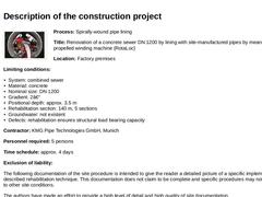
(Image: 379206 - Titelbild Dokumentation) Process: Spirally-wound pipe lining Title: Renovation of a concrete sewer DN 1200 by lining with site-manufactured pipes by means of a self-propelled winding machine (RotaLoc) Location: Factory premises Limiting conditions: - System: combined sewer
- Material: concrete
- Nominal size: DN 1200
- Gradient: 2‰
- Positional depth: approx. 3.5 m
- Rehabilitation section: 140 m, 5 sections
- Groundwater: not existent
- Defects: …
|
|

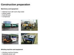
Machinery and equipment - Material truck with work shop trailer
- Wheel loader
- Fork-lift truck
- Compressor
| (Image: Material truck with work shop trailer) | (Image: Wheel loader) | | (Image: Fork-lift truck) | (Image: Compressor for power supply at the starting manhole) |
Winding machine and equipment - Winding machine Rotaloc
- Hydraulic power unit
- Control unit
- Cable drum with supply cable
- Drum skid including drive for rotating the material drum with the PVC profile
|
|

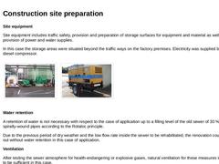
Site equipment Site equipment includes traffic safety, provision and preparation of storage surfaces for equipment and material as well as the provision of power and water supplies. In this case the storage areas were situated beyond the traffic ways on the factory premises. Electricity was supplied by means of a diesel compressor. | (Image: Construction site arrangement) | (Image: Compressor for power supply at the target manhole) |
Water retention A retention … |
|

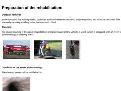
Obstacle removal In the run-up to the relining works, obstacles such as hardened deposits, projecting inlets, etc. must be removed. This is done manually by using a milling cutter, hammer and chisel. Cleaning For sewer cleaning in this case of application a high pressure jetting vehicle is used, which is equipped with an invert jet that has a particularly good clearing effect. | (Image: Cleaning of the sewer with a high-pressure jetting vehicle) | (Image: … |
|
|

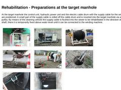
At the target manhole the control unit, hydraulic power unit and the electric cable drum with the supply cable for the winding machine are positioned. A small part of the supply cable is rolled off the cable drum and is inserted into the target manhole via an deflexion pulley. By means of the cleaning vehicle the supply cable is flushed into the sewer to be rehabilitated in the direction of the starting shaft; there it is temporarily fixed above … |
|

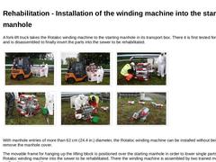
A fork-lift truck takes the Rotaloc winding machine to the starting manhole in its transport box. There it is first tested for completeness and is disassembled to finally insert the parts into the sewer to be rehabilitated. | (Image: Transport of the winding machine to the starting manhole) |
(Image: Removal of the winding machine from the transport box) |
(Image: Disassembly of the winding machine into its components) |
| (Image: Disassembly of the winding … |
|
|

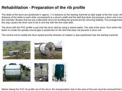
The skids of the drum are positioned in approx. 1 m distance to the starting manhole at right angle to the line route, whereas the distance of the skids to each other corresponds to a drum's width and the skid that does not possess a drive unit is turned towards the manhole. Boards that are put underneath serve for levelling the ground and for ensuring stability. The arrangement of the skids in this way causes the drum axis to be in one line with … |
|

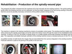
The prepared rib profile is lowered into the manhole and is fed manually into the winding machine. The spiral guiding (helix) of the profile within the winding machine can be calibrated, so that the proper snapping of the lock during winding is ensured. A slide hammer serves for possibly necessary corrections of the profile's position during starting. | (Image: Insertion of the prepared rib profile into the starting manhole) | (Image: Insertion of the … |
|
|

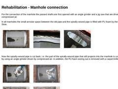
For the connection of the manhole the passed shafts are first opened with an angle grinder and a jig saw that are driven by compressed air. In all manholes the small annular space between the old pipe and the spirally-wound pipe is filled with PU foam by the company Sista. | (Image: Intermediate manhole with opened up spirally-wound pipe) | (Image: Annular space filled with PU foam) | (Image: Annular space filled with PU foam) |
Now the spirally-wound pipe … |
|

The side inlets that were measured before the rehabilitation are opened and connected manually. By means of the angle grinder and the jig saw first the side inlets are exposed. Like the manhole connection, the narrow annular space between the old sewer and the spirally-wound pipe is filled with PU foam and plugged up with sealing mortar. |

|

The profile butt joints that have developed due to the drum change must be re-worked. The thus developed joint gaps must also be filled with PU foam, the surrounding spirally-wound pipe must be roughened with an angle grinder and afterwards the joint region must be laminated with mats soaked with epoxy resin. |

|

To check the success of the rehabilitation, an optical inspection by accessing the sewer as well as a leaktightness test according to DIN EN 1610 are carried out. |
|

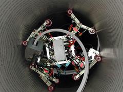
Lining of a DN 1200 concrete sewer with a profiled plastic profile with lock, which is wound in a spiral using a self-propelled winding machine, and forms a continuous pipe string after installation (RotaLoc). |