|
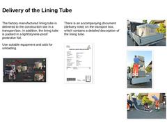
The factory-manufactured lining tube is delivered to the construction site in a transport box. In addition, the lining tube is packed in a light/styrene-proof protective foil. Use suitable equipment and aids for unloading. (Image: Unloading the transport box with crossbeam ) There is an accompanying document (delivery note) on the transport box, which contains a detailed description of the lining tube. (Image: Delivery note on a transport box) |
|
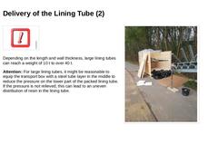
Important: Depending on the length and wall thickness, large lining tubes can reach a weight of 10 t to over 40 t. Attention: For large lining tubes, it might be reasonable to equip the transport box with a steel tube layer in the middle to reduce the pressure on the lower part of the packed lining tube. If the pressure is not relieved, this can lead to an uneven distribution of resin in the lining tube. (Image: Transport box with steel tube layer … |
|
(Image: Picto Sonneneinstrahlung Sonnenlicht 2022) Store the lining tube in the transport box until it is pulled in. Take the following points relating to UV radiation into consideration: -
The lining tube reacts to UV radiation, leading to an exothermic reaction. This can result in temperatures of up to 120 °C or greater.
-
The light protection foil protects the lining tube against the UV radiation present in ambient light and prevents unwanted curing.
|
|
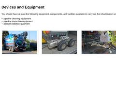
You should have at least the following equipment, components, and facilities available to carry out the rehabilitation works: -
pipeline cleaning equipment
-
pipeline inspection equipment
-
possibly robotic equipment
(Image: Suction / flushing vehicle with water recovery) (Image: CCTV inspection camera with attached pull cable) (Image: Milling robot for opening the lateral connections 6) |
|
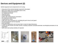
Vehicle equipment and components for UV curing: -
lining tube of the nominal diameter required for the project
-
light source (light source chain/light source core)
-
temperature measuring sensors
-
UV replacement lamps
-
sling and swivel
-
shut-off elements
-
packer with compressed air connections
-
air compressor and/or blower
-
compressed air hoses
-
cable winch with mechanism for controlling the pull-in forces and speed
-
tool and equipment room (if required)
|

|
|
|
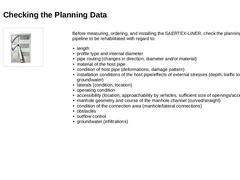
Before measuring, ordering, and installing the SAERTEX-LINER, check the planning data for the pipeline to be rehabilitated with regard to: -
length
-
profile type and internal diameter
-
pipe routing (changes in direction, diameter and/or material)
-
material of the host pipe
-
condition of host pipe (deformations, damage pattern)
-
installation conditions of the host pipe/effects of external stresses (depth, traffic load, soil type, …
|
|
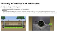
Carefully work through the following points: -
Check the planning data and details on the specifications.
-
Measuring
-
Determine the length to order. Take any accuracy tolerances of your measuring instrument into consideration.
-
Determine the internal diameter: determine it at least at four positions on both ends of the pipe and calculate the mean value.
(Image: Determining the length to order) (Image: Determining the internal diameter of the circular … |

|
Carefully work through the following points: -
Do not take measurements at socket ends. Taking measurements at the socket end can lead to incorrect values.
-
If deviations from the circular profile or the egg-shaped profile occur, determine the exact internal circumference of the pipeline, e.g., using a measuring tape (see Special Profiles too).
-
For analysis purposes, carry out a laser-assisted deformation measurement over the entire length of the …
|

|
-
Clean the pipeline immediately before the pull-in of the lining tube by means of high-pressure flushing.
-
Remove all obstacles (connections, deposits, roots, incrustations, water/wastewater in the area of sag bends, etc.) that are not flush with the inside of the pipeline under rehabilitation.
-
A visual inspection must be made using digital means in order to ensure and verify the absence of obstructions. Such verification shall be submitted, e.g. …
|
|
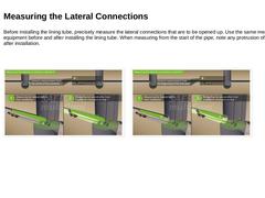
Before installing the lining tube, precisely measure the lateral connections that are to be opened up. Use the same measuring equipment before and after installing the lining tube. When measuring from the start of the pipe, note any protrusion of the CIPP liner after installation. (Image: Measuring the lateral connections in accordance with schema A ) (Image: Measuring the lateral connections in accordance with schema B) |
|
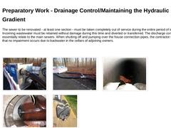
The sewer to be renovated - at least one section - must be taken completely out of service during the entire period of installation. Incoming wastewater must be retained without damage during this time and diverted or transferred. The discharge control measures essentially relate to the main sewers. When shutting off and pumping over the house connection pipes, the contractor shall ensure that no impairment occurs due to backwater in the cellars … |

|
|
|
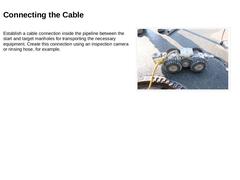
Establish a cable connection inside the pipeline between the start and target manholes for transporting the necessary equipment. Create this connection using an inspection camera or rinsing hose, for example. (Image: CCTV inspection camera with attached pull cable ) |
|
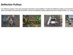
Use deflection pulleys in the start and target manholes to aid installation. Position the deflection pulleys such that the lining tube, ropes, and cables are protected at all times. Secure the deflection pulleys against the forces acting on them, e.g. using screw jacks. (Image: Rope and deflection pulley ) (Image: Manhole deflection pulley for chain of lights) (Image: Deflection pulley for manhole channel with screw jacks (spindles) for securing ) (… |
|
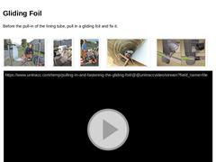
Before the pull-in of the lining tube, pull in a gliding foil and fix it. (Image: Preparation of the gliding foil for the pull-in) (Image: Raised and prepared gliding foil) (Image: Pulling in the gliding foil) (Image: View into the manhole during the pulling in of the gliding foil) (Image: Fixation of the gliding foil ) (Video: Pulling in and fastening the gliding foil ) (Video: Pulling in the gliding foil from manhole to manhole) |
|
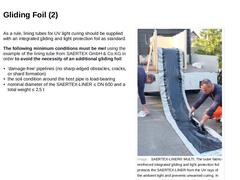
As a rule, lining tubes for UV light curing should be supplied with an integrated gliding and light protection foil as standard. The following minimum conditions must be met using the example of the lining tube from SAERTEX GmbH & Co.KG in order to avoid the necessity of an additional gliding foil: -
‘damage-free’ pipelines (no sharp-edged obstacles, cracks, or shard formation)
-
the soil condition around the host pipe is load-bearing
-
nominal diameter …
|
|
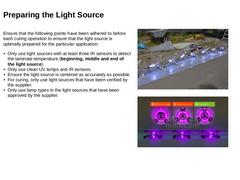
Ensure that the following points have been adhered to before each curing operation to ensure that the light source is optimally prepared for the particular application: -
Only use light sources with at least three IR sensors to detect the laminate temperature (beginning, middle and end of the light source).
-
Only use clean UV lamps and IR sensors.
-
Ensure the light source is centered as accurately as possible.
-
For curing, only use light sources that …
|
|
(Image: Picto Liste) Ensure that the following points have been adhered to before each curing operation to ensure that the light source is optimally prepared for the particular application: -
Document the time of first use.
-
Regularly check the intensity of the UV lamps; this must initially be carried out after 400 operating hours. Thereafter, check each UV lamp after every 150 additional operating hours.
-
Perform a comparative measurement (intensity …
|
|
What needs to be measured and recorded? -
electronic recording of the pulling speed of the UV light chain, of the spot function (on/off)
-
electronic measurement and recording of the temperature curves in the surface area of the liner while the UV light chain is being pulled through
-
measurement of the radiation intensity while the UV light chain is being pulled through for curing
-
measurement of the installation pressure (internal …
|

|
|
|
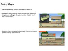
Observe the following points to ensure a proper pull-in. -
Where the safety caps are factory-installed, pay attention to the planned pulling-in direction (position of cable winch and transport box).
(Image: Factory pre-assembled safety cap – planned pulling-in direction) -
Be aware that an irregular feed pulling-in direction can cause product damage or even failure.
(Image: Factory pre-assembled support sleeve – irregular pulling-in direction) |
|
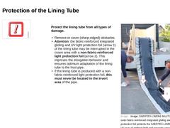
Protect the lining tube from all types of damage. -
Remove or cover (sharp-edged) obstacles.
-
Attention: the fabric-reinforced integrated gliding and UV light protection foil (arrow 1) of the lining tube may be interrupted in the crown area with a non-fabric-reinforced light protection foil (arrow 2). This improves the elongation behavior and ensures optimum adaptation of the lining tube to the host pipe.
-
If the lining tube is produced …
|
|
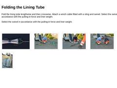
Fold the lining tube lengthwise and then crosswise. Attach a winch cable fitted with a sling and swivel. Select the swivel in accordance with the pulling-in force and liner weight.
Select the swivel in accordance with the pulling-in force and liner weight. (Image: Folded lining tube with sling and swivel ) (Image: Folding the lining tube head and assembling the sling and the swivel 2) (Image: Folding the lining tube head and assembling the sling and … |
|
-
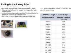
Pull in the lining tube with a maximum speed of 5 m/min.
-
Maximum pull-in forces are listed in a corresponding table (see example).
-
If necessary, biologically degradable oil can be applied to the gliding foil to reduce the pulling-in forces.
-
Pull in the lining tube against the direction of the flow.
(Image: Starting the cable winch for pulling in the lining tube) (Image: Display of the winch) (Image: Display of the winch - pulling force in [kN] … |