|
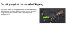
Secure the end of the lining tube against uncontrolled slipping. Carefully lower the lining tube end into the manhole or trench using an excavator, crane or pull-in support equipment (conveyor belt). (Image: Fall protection at the lining tube end) |
|
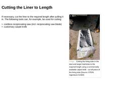
If necessary, cut the liner to the required length after pulling it in. The following tools can, for example, be used for cutting: -
cordless reciprocating saw (incl. reciprocating saw blade)
-
customary carpet knife
(Image: Cutting the lining tube in the start and target manholes to the required length using a commercially available carpet knife - cut off piece of the lining tube) |
|
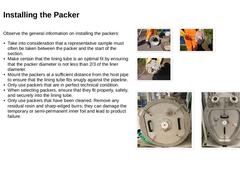
Observe the general information on installing the packers: -
Take into consideration that a representative sample must often be taken between the packer and the start of the section.
-
Make certain that the lining tube is an optimal fit by ensuring that the packer diameter is not less than 2/3 of the liner diameter.
-
Mount the packers at a sufficient distance from the host pipe to ensure that the lining tube fits snugly against the pipeline.
-
Only use …
|
|
-
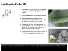
Open the end of the lining tube to create a full opening that allows the packer to be inserted.
-
Slide the packer into the resulting opening.
-
Slide the packer inside the inner foil (temporary or semi-permanent) until it can be securely and firmly fixed in place.
-
Ensure that no large folds are formed. Fix the lining tube to the packer below the light protection foil using at least two ratchet straps or stainless-steel straps.
|
|
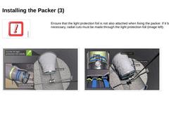
Ensure that the light protection foil is not also attached when fixing the packer. If it becomes necessary, radial cuts must be made through the light protection foil (image left). (Image: Fixing the packer above the light protection foil – Note: Illustration shows the radially cut light protection foil ) (Image: Securing packers ) |
|
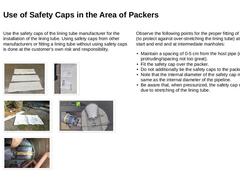
Use the safety caps of the lining tube manufacturer for the installation of the lining tube. Using safety caps from other manufacturers or fitting a lining tube without using safety caps is done at the customer’s own risk and responsibility. (Image: Safety caps for different diameters ) (Image: Safety cap DN 515 with article number) (Image: Safety caps for DN 400) (Image: Fixing the packer above the light protection foil – Note: Illustration shows … |

|
|
|
-
Switch on the recording function before applying pressure to the lining tube.
-
Document the entire inflation and curing phase.
-
Only use UV systems that are equipped with a digital data recorder.
-
Record the following values in real-time throughout the entire installation period:
-
internal pressure
-
function of the individual lamps
-
firing intervals and curing speeds
-
temperatures on the inner surface of the liner
-
date and …
|
|
-
Only perform work inside structures/manholes/trenches at a maximum internal pressure (inside the lining tube) of 50 mbar!
-
Note that when using a blower, the compressed air entering the lining tube can become very hot.
-
Avoid a premature curing reaction and damage to the inner foil (temporary or semi-permanent) caused by introducing compressed air that is too hot (e.g., when ambient air temperatures are too high).
-
The temperature of …
|
|
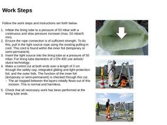
Follow the work steps and instructions set forth below. -
Inflate the lining tube to a pressure of 50 mbar with a continuous and slow pressure increase (max. 50 mbar/5 min).
-
Ensure the rope connection is of sufficient strength. To do this, pull in the light source rope using the existing pulling-in cord. This cord is found within the inner foil (temporary or semi-permanent).
-
Insert the light source into the lining tube at a pressure of 50 mbar. For …
|
|
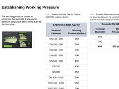
The working pressure serves to compress the laminate and ensures optimum adaptation of the lining tube to the host pipe. (Image: Establishing working pressure - serves to compress the laminate and ensures optimum adaptation of the lining tube to the host pipe ) (Table: Working Pressure Type S+) (Table: Example: Determining the working pressure for dimension between the specified diameters ) |
|
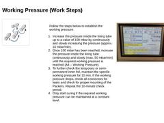
Follow the steps below to establish the working pressure. -
Increase the pressure inside the lining tube up to a value of 100 mbar by continuously and slowly increasing the pressure (approx. 10 mbar/min).
-
Once 100 mbar has been reached, increase the pressure inside the lining tube continuously and slowly (max. 50 mbar/min) until the required working pressure is reached (A4 – Working Pressure).
-
To further check the temporary or semi-…
|
|
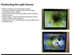
-
Position the light source at the target manhole.
-
Now, manually pull in the light source from the target manhole to the start manhole.
-
Do not switch on the camera illumination until immediately before the pull-in.
-
When pulling in, check for optimal fit and flawless internal surface condition of the lining tube.
-
Ensure that the liner outside the pipe is linearly aligned with the pipeline axis.
(Image: Manually pulling in the light chain source … |
|
-
Before curing, check that the UV system/light source is suitable for the application. Confirm that the specific ignition intervals and curing speeds are available.
-
Establish the basic requirements to ensure full functionality of the UV system throughout the curing process. Failure of the UV system may result in damage to the product or even product failure.
-
Maintain the working pressure at a constant level throughout the entire curing process (…
|
|
-
Adhere to the individual curing speeds and surface temperatures.
-
Note that the surface temperature of the lining tube must be between 80 – 120 °C when using a minimum of two IR sensors.
-
Cure the lining tube at the minimum curing speed (lower value from the parameter table) if the minimum temperature of 80 °C is not reached when using two IR sensors.
-
Increase the curing speed by 10 % to the specified maximum curing speed (higher value from the …
|
|
|
|
Take into consideration that the ignition intervals and speeds to be used depend on the dimensions, wall thickness, and resin system of the lining tube. In the following, 4 ignition schemes with the designation A, B, C, and D are presented. The choice of the ignition scheme as well as the (minimum) pulling-in speed is coordinated with the supplier on the basis of specific parameter tables depending on the above-mentioned parameters. Each ignition … |
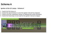
|
Ignition of the UV Lamps – Schema A
-
Switch the first lamp on.
-
Switch the second lamp on once the ignition interval has elapsed.
-
Switch all of the subsequent lamps on following the same procedure.
-
Switch the final lamp on and wait for the ignition interval to elapse.
(Image: Ignition of the UV Lamps – Schema A ) |
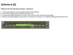
|
Pulling in the UV Light Source Chain – Schema A
-
Commence pulling in once the ignition process has finished.
-
Pull in with a speed of 35 cm/min for the first 0.5 m.
-
Increase the speed stepwise (70 cm/min; 105 cm/min) to the minimum curing speed.
-
Reduce the speed stepwise (105 cm/min; 70 cm/min; 35 cm/min) 1.5 m before reaching the end of the liner.
(Image: Minimum curing speed - Schema A) |
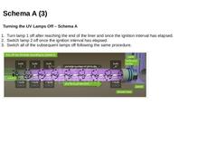
|
Turning the UV Lamps Off – Schema A
-
Turn lamp 1 off after reaching the end of the liner and once the ignition interval has elapsed.
-
Switch lamp 2 off once the ignition interval has elapsed.
-
Switch all of the subsequent lamps off following the same procedure.
(Image: Turning the UV Lamps Off – Schema A) |
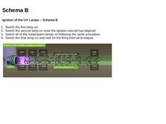
|
Ignition of the UV Lamps – Schema B -
Switch the first lamp on.
-
Switch the second lamp on once the ignition interval has elapsed.
-
Switch all of the subsequent lamps on following the same procedure.
-
Switch the final lamp on and wait for the firing interval to elapse.
(Image: Ignition of the UV Lamps – Schema B) |
|
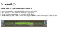
Pulling in the UV Light Source Chain – Schema B -
Commence pulling in once the ignition process has finished.
-
Pull the first 0.5 m in at half the minimum curing speed.
-
Then increase the speed to the minimum curing speed.
-
Reduce the speed to half the minimum curing speed 0.5 m before reaching the end of the liner.
(Image: Minimum pulling in speed - Schema B ) |
|
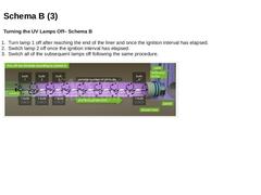
Turning the UV Lamps Off– Schema B
-
Turn lamp 1 off after reaching the end of the liner and once the ignition interval has elapsed.
-
Switch lamp 2 off once the ignition interval has elapsed.
-
Switch all of the subsequent lamps off following the same procedure.
(Image: Turning the UV Lamps Off – Schema B) |
|
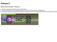
Ignition of the UV Lamps – Schema C
-
Switch on the lamps of the first core simultaneously.
-
After the ignition interval has elapsed, switch on the lamps of the next core simultaneously.
-
If there are more than two elements repeat this procedure until all cores have ignited and wait for the ignition interval to elapse.
(Image: Ignition of the UV lamps – Schema C ) |
|
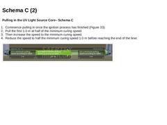
Pulling in the UV Light Source Core– Schema C
-
Commence pulling in once the ignition process has finished (Figure 33).
-
Pull the first 1.0 m at half of the minimum curing speed.
-
Then increase the speed to the minimum curing speed.
-
Reduce the speed to half the minimum curing speed 1.0 m before reaching the end of the liner.
(Image: Minimum pulling in speed - Schema C) |