|
Mar 09, 2021
News
Lori McCormick
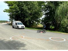
Infrasense recently completed a ground penetrating radar (GPR) survey to map the location of a surface drainage oil/water separator structure below a recently paved road.
|
|
Mar 19, 2021
News
Lila Thompson
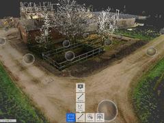
As the water sector continues its shift from constructing new infrastructure to improving performance of existing assets, full adoption of building information management (BIM) tools is critical to success. Approaching year two of the AMP7 investment cycle, BIM4Water vice-chair and MWH Treatment national rehearsal lead Clare Kovacs discusses the outlook for widescale digital implementation.
|

|
This course features elements relevant to amongst others the European continent. This course includes neither tutorial services nor a final examination. This course is available free of charge. To access it, please register on UNITRACC.com.
----------------------- The most common method utilized worldwide for pipeline installation is the open cut method. This is especially true for gravity pipelines. While, at first glance, the open cut method seems to be a "simple" constructon method, it becomes highly complex when used in urban areas and at large depths. This course is divided into two parts: - The first part is focused on important technical knowledge on securing the trench and making it a safe work zone. It presents the many options available in this regard.
- The second part is focused on the correct pipeline installation techniques including backfilling of the trench and the removal of the shoring.
The net learning time is approx. 3 days. |

|
This course features elements relevant to amongst others the North-American continent. This course includes neither tutorial services nor a final examination. This course is available free of charge. To access it, please register on UNITRACC.com.
----------------------------- The most common method utilized worldwide for pipeline installation is the open cut method. This is especially true for gravity pipelines. While, at first glance, the open cut method seems to be a "simple" constructon method, it becomes highly complex when used in urban areas and at large depths. This course is divided into two parts: - The first part is focused on important technical knowledge on securing the trench and making it a safe work zone. It presents the many options available in this regard.
- The second part is focused on the correct pipeline installation techniques including backfilling of the trench and the removal of the shoring.
The net learning time is approx. 3 days. |

|
Dec 22, 2020
News
Heather Centorbi
Organizers have announced the 5th annual Risk Management in Underground Construction course will take place virtually April 13-15, 2021.
|

|
Dec 07, 2022
News
Trenchless Australasia
Utilities company Gippsland Water is securing the water and wastewater future for the towns of Warragul and Drouin as part of the western ring main project.
|
|
Summary: This module teaches the basics of geophysical soil investigation and is to be understood as a supplement to the module "Geotechnical Investigation". Geophysical measurement methods belong to the indirect exploration methods and allow statements regarding local inhomogeneities in the pipeline zone (e.g. bedding defects, cavities, disruptions, concrete encasements) or, in the case of investigations of existing sewers and pipelines, statements … |
|
During damage assessment, but also in the decision for a suitable rehabilitation method, sound knowledge of the bedding conditions of the existing sewer is very important, because, in many cases, these conditions represent the causes of damage. Large-scale insights on the -
condition of the bedding
-
load bearing capacity of the bedding
-
information on local inhomogeneities such as (bedding defects, cavities, concrete casings)
can be gained by means … |

|
The following simplified description of the methods is limited to a selection of geophysical methods of measurement that (with respect to the problem of subsurface investigation as a part of sewer rehabilitation and maintenance methods) can be applied either from the ground surface or from vertical boreholes. Depending on the individually chosen method, information can be provided about: -
The position of the sewer,
-
The geological and hydrogeological …
|
|
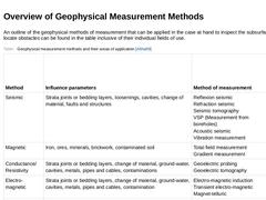
An outline of the geophysical methods of measurement that can be applied in the case at hand to inspect the subsurface and to locate obstacles can be found in the table inclusive of their individual fields of use. (Table: Geophysical measurement methods and their areas of application) |
|
Seismic technology is by far the most important and prevailing method of exploratory geophysics used to explore deposits such as oil, gas and coal. From an (environmental) engineering point of view, it also provides essential structural information. In seismic methods, elastic waves and wave fields are used as information carriers which can be processed into images of the subsurface. This makes it possible to gain a direct insight into its complex … |

|
The underground has an impact on the propagation of seismic (elastic) waves by mechanisms such as: reflection, refraction, diffraction, absorption and scattering. The seismic waves (1) for these analyses are produced artificially (2), e.g. through explosions, blows of a hammer, speakers, vibrators and implosions, and then usually recorded via electro-dynamic receivers (3) (geophones) after they have traversed the underground. The waves that propagate … |

|
Seismic methods can be of help in solving the following tasks: -
Mapping of strata borders,
-
Mapping of density differences,
-
Determination of elastic parameters,
-
Exploration of the bedding and side filling,
-
Location of bedding defects and objects in the embedment (remains of lining such as sheet piles, planks, foundations, random blocks, lines, roots etc.),
-
Exploration of roots.
Seismic measurement methods Seismic measurement methods … |
|
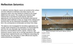
In reflection seismics (figure), waves are excited at the surface and then reflected at interfaces (boundary layers), and registered within only short distances (relative to the target depth) from the source. The usually very extensive data material that is recorded by multi-channel, telemetric apparatuses can be processed and illustrated using special computer-aided methods to show an image of the underground structure that can be interpreted immediately. … |
|
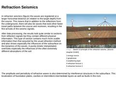
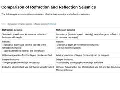
In refraction seismics (figure) the waves are registered at a larger horizontal distance (in relation to the target depth) from the source. This means that in addition to the reflections from the underground, there will also be waves that took other faster travel paths between the source and receivers, resulting in the first arrivals of the seismic signals. After data processing, the results look quite similar to sections from reflection signals but … |
|
The following is a comparative comparison of refraction seismics and reflection seismics. (Table: Comparison refraction seismic - reflexion seismic [FI-Steina]) |
|
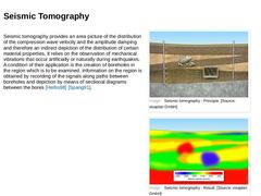
Seismic tomography provides an area picture of the distribution of the compression wave velocity and the amplitude damping and therefore an indirect depiction of the distribution of certain material properties. It relies on the observation of mechanical vibrations that occur artificially or naturally during earthquakes. A condition of their application is the creation of boreholes in the region which is to be examined. Information on the region is … |
|
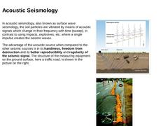
In acoustic seismology, also known as surface wave seismology, the soil particles are vibrated by means of acoustic signals which change in their frequency with time (sweep), in contrast to using impacts, explosives, etc. where a single impulse creates the seismic waves. The advantage of the acoustic source when compared to the other seismic sources is in its handiness, freedom from destruction and its better reproducibility and regularity of the … |

|
|
|
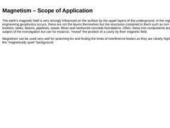
The earth’s magnetic field is very strongly influenced on the surface by the upper layers of the underground. In the region in which engineering geophysics occurs, these are not the layers themselves but the structures contained in them such as iron components, bunkers, tanks, beams, pipelines, waste, fibres and reinforced concrete foundations. Often, these iron components are not the subject of the investigation but can for instance, “reveal” the … |

|
The physical principle of measurement is shown in the figure. The anomaly field can be found in the top half of the image, whereas the lower half represents the formation of the total field by vector addition of the natural Earth’s field with the field of an interference body (anomaly field). At the level of the observation (here as side view) the magnetic anomaly can be observed [Lenz97]. (Image: Physical principle of measurement of magnetism [Lenz1997] - … |

|
In the process of Electromagnetic Induction (EMI), the subsurface is subjected to an alternating field by means of a coil and this induces a secondary field. This, again, superimposes itself on the exciting field. The resulting field is measured by a receiver coil. The images show the manual measurement. The frequency used in the EMI method ranges from about 10 Hz to 2 MHz, the spacing between the coils varies from just a few metres up to about 100 … |

|
|

|
Geoelectrics are used to locate objects and structures that have a different electrical resistance than their environment. A distinction can be made between galvanic and capacitive geoelectrics. In the first case, the electrodes and measuring probes are put into the ground in the form of metal stakes and thus galvanically coupled. In the case of the capacitive coupled geoelectrics, the electrodes are made of a metallic cable that is isolated against … |
|
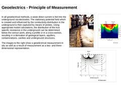
In all geoelectrical methods, a weak direct current is fed into the underground via electrodes. The stationary potential field which is created and influenced by the conductivity distribution in the underground is then captured by means of probes. Using appropriate model calculations, the distribution of the true specific resistance in the underground can be determined below the sensor point, along a profile or in a cross-section, resulting in a … |