|

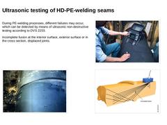
During PE-welding processes, different failures may occur, which can be detected by means of ultrasonic non-destructive testing according to DVS 2203. Incomplete fusion at the interior surface, exterior surface or in the cross section, displaced joints. (Image: Conventional sliplining process with annular space [FI-Teerb] - Testing the welded seam) (Image: Conventional sliplining process with annular space [FI-Teerb] - View on the complete welding joint) |
|

|
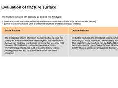
The fracture surfaces can basically be divided into two types: - brittle fractures are characterised by smooth surfaces and indicate poor or insufficient welding
- ductile fracture surfaces have a stretched structure and indicate good welding
| Brittle fracture | Ductile fracture | |
The molecular chains of smooth fracture surfaces could not or only to a very small extent intermingle in the interfaces of the two join partners (e.g. by join partners that were … |
|
|

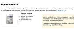
Welding work has to be monitored. The type and extent of supervision has to be agreed upon between the contract partners. It is recommended to document the method information in welding protocols or on data media [DVSR2207-1]. (Image: Documentation) Welding protocol -
Melting temperature
-
Melting time
-
Jointing pressure
As the welder knows the nominal values from the regulations and standards, these values will always remain within the stipulated tolerances. |

|

-
Wrong calculation of the welding pressure
-
Non-observance of the heating-up time, relocation time or preparation time of joining pressure
-
Non-observance of welding temperature (too high or too low)
-
Machine is defect
-
Machine is not calibrated
-
Chosen welding pressure cannot be maintained (e.g. because of leaky piston connection)
-
Contaminated joint surfaces
-
Wrong material matching
-
Material residues at heated tool
|
|

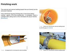
The external and internal welding beads that are formed can be removed if desired. If the weld bead requires finishing this is best done before cooling – approx. 2/3 of the cooling time – is complete. There is a danger that cutting work on the cold bead will cause notches [Simona11]. (Image: Device for removing the internal welding bead for HD-PE pipes [FI-WIDOS]) (Image: Arrangement for removing the internal welding bead for HD-PE pipes (Locheisen) … |
|

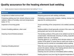
(Table: Quality assurance measures during heated element butt welding) |
|

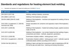
(Table: Standards and regulations for heated tool welding (as of 12/2005) [FI-Steina]) |

|

|
|

|
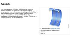
(Image: Electrofusion fitting)
The external surface of the pipe and the internal side of the electrofusion fitting are heated up to the required welding temperature by means of resistance wires integrated in the fitting in that they are stressed by electric current. In doing so, both components produce fused material. After the cooling, an inseparable, homogeneous connection is created. This method is used at present for PE-HD and PP pipes. |
|
|

|
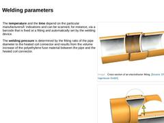
(Image: Cross section of an electrofusion fitting) |
|
(Image: Detail of the electrofusion fitting) |
The temperature and the time depend on the particular manufacturersÂ’ indications and can be scanned, for instance, via a barcode that is fixed at a fitting and automatically set by the welding device. The welding pressure is determined by the fitting ratio of the pipe diameter to the heated coil connector and results from the volume increase of the … |
|
|

-
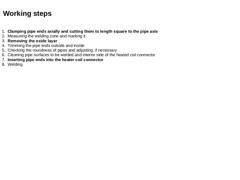
Clamping pipe ends axially and cutting them to length square to the pipe axis
-
Measuring the welding zone and marking it
-
Removing the oxide layer
-
Trimming the pipe ends outside and inside
-
Checking the roundness of pipes and adjusting, if necessary
-
Cleaning pipe surfaces to be welded and interior side of the heated coil connector
-
Inserting pipe ends into the heater coil connector
-
Welding
|
|
|

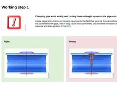
Clamping pipe ends axially and cutting them to length square to the pipe axis A pipe separation that is not square may lead to the fact that parts of the electrofusion coils are not covered by the pipe, which may cause excessive heat, uncontrolled formation of melting material and auto-ignition [Friatec04]. Right (Image: Electrofusion welding – square pipe separation according to [FI-Friat]) Wrong (Image: Electrofusion welding pipe … |
|

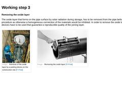
Removing the oxide layer The oxide layer that forms on the pipe surface by solar radiation during storage, has to be removed from the pipe before any welding procedure as otherwise a homogeneous connection of the materials would be inhibited. In order to remove the oxide layer, peeling devices have to be used that guarantee a reproducible quality of the joining layer. (Image: Removal of the oxide layer by a peeling device on the construction site [… |
|

|
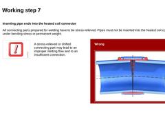
Inserting pipe ends into the heated coil connector All connecting parts prepared for welding have to be stress-relieved. Pipes must not be inserted into the heated coil connector under bending stress or permanent weight. |
|
(Image: Attention!)
A stress-relieved or shifted connecting part may lead to an improper melting flow and to an insufficient connection. |
Wrong (Image: Electrofusion welding -– tilted pipes according to [FI-Friat]) |
|

|

-
Installations in regions that are difficult to access
-
Repairs in which the pipes cannot be moved or only to a limited extent
-
Tapping valves
-
Single applications that do not justify the high costs for the heating element butt welding
|
|

|

|
Process data for heater coil welding according to ISO/TR 13950 -
Manufacturer
-
Type (e.g. tapping clamp)
-
Diameter
-
Welding stress
-
Welding time
-
Adjustment of welding time depending on the environmental temperature
-
Cooling-off time
-
Resistance of heated coil
-
Manufacturing tolerance and temperature tolerance of the heated coils (temperature coefficient)
|
|
|

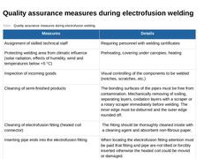
(Table: Quality assurance measures during electrofusion welding) |
|

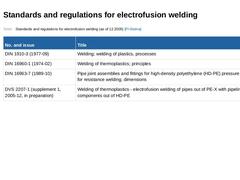
(Table: Standards and regulations for electrofusion welding (as of 12.2005) [FI-Steina]) |
|

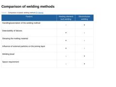
(Table: Comparison of plastic welding methods) |

|

|
|

|
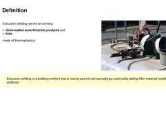
(Image: Welding of the liner ends by means of Extruder welding - Extruder with welding additive)
Extrusion welding serves to connect -
thick-walled semi-finished products and
-
foils
made of thermoplastics. |
|
Extrusion welding is a welding method that is mainly carried out manually by continually adding filler material (welding additive). |
|
|

|
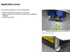
(Image: Watertight welding of the stud course and Preliner) |
|
(Image: Extruder-welding device – end of welding procedure) |
The method is applied e.g. in the following fields: -
Plant construction and container construction
-
Pipeline construction and sewer construction (rehabilitation methods)
-
Landfill construction
|
|
|

|
(Image: Temperature) |
In order to balance the temperature differences between the components to be welded, the components have to be stored before the welding procedure under the same conditions for a sufficient period of time. |
|
|

|
(Image: Attention!)
The joint faces and adjacent edges must be machined before welding (e.g. with a grinder). |
|
|
|
Regions damaged by climatic or chemical influence have to be reduced down to the undamaged zone. No detergents that have swelling effects on plastics may be used for cleaning the joining areas. |
(Image: Roughening the stud course for later welding) |
|
|

|
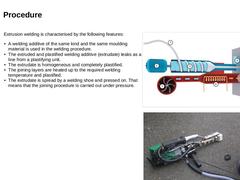
(Image: Schematic view of an extruder) |
|
(Image: Extruder-melting device) |
Extrusion welding is characterised by the following features: -
A welding additive of the same kind and the same moulding material is used in the welding procedure.
-
The extruded and plastified welding additive (extrudate) leaks as a line from a plastifying unit.
-
The extrudate is homogeneous and completely plastified.
-
The joining layers are heated up to the required welding …
|
|