
|
|
|
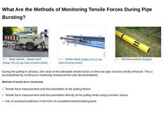
(Image: Target manhole - capstan winch) (Image: Overload protection [Jürge05]) During the pulling-in process, the value of the allowable tensile forces on the new pipe must be strictly enforced. This is accomplished by continuous monitoring (measurement and documentation). Methods of tensile force monitoring: |
|
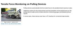
(Image: Target manhole - capstan winch) Pulling devices automatically limit the tensile force to the predetermined maximum value. Additional systems for the measurement and documentation of the tensile forces on the pulling device (cable winch) include electronic monitoring gauges and detailed printout reports. In some cases, these devices also have a PC interface for convenient data transfer. |
|
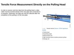
In order to receive real time data from the pulling head, a data cable must be inserted ahead of the new pipe and connected to a computer. Otherwise, the data can only be collected after the completion of the pulling-in of the new pipe. |
|
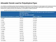
As a reference, the following table shows the allowable tensile forces for PE 100 pipes for a load duration of 30 minutes (according to the German DVGW working sheet GW 323: Trenchless replacement of gas and water supply pipelines with pipe bursting; Requirements, quality assurance and inspections / not available in English at present). (Table: Allowable tensile forces for PE 100 pipes under a 30 min load) |
|
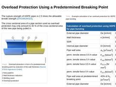
The rupture strength of HDPE pipes is 2.5 times the allowable tensile strength [DVGWGW323]. The cross sectional area of a pipe section used as overload protection may only amount to 40 % of the cross sectional area of the new pipe being pulled in. (Image: Overload protection in form of a predetermined breaking point by reduction of the wall thickness) (Table: Example calculation of an overload protection for HDPE 100 used in pipe bursting) |
|
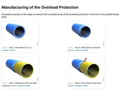
Illustrated example of the steps involved in the manufacturing of the overload protection in the form of a predetermined breaking point. (Image: Step 1: New pipeline) (Image: Step 2: Wall thickness reduction) (Image: Step 3: Welding on of the overload protection) (Image: Step 4: Removing the weld seam) |
|
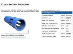
A cross section reduction is obtained by reducing the effective circumference of the pipe or the effective cross-sectional area. (Image: Overload protection in form of a predetermined breaking point by reduction of the effective pipe circumference) (Table: Overload protection) |
|
|
|
Congratulations! You have successfully finished this module. Next you will have the opportunity to review the newly acquired knowledge with an interactive questionnaire. You can navigate back to any point in the lessons if you wish to review a specific point or subject. Stay curious! |
|
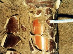
This module is devoted to the pipe bursting as a special method of the replacement of pipelines. In addition, the module looks at the material and equipment requirements and the effects that pipe bursting has on the pipeline itself as well as its surrounding environment. Upon the successful completion of this module, you will be able to: - describe the various pipe bursting processes,
- identify the effects of pipe bursting on the surrounding environment, and
- calculate the required minimum distances to the adjacent utilities and structures.
|
|
This lecture deals with the fundamentals of trenchless replacement of supply and disposal lines by means of gallery techniques (heading). |
|
|
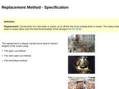
Definition Replacement: Construction of a new drain or sewer, on or off the line of an existing drain or sewer. The newly installed drain or sewer takes over the load (functionality) of the old pipe [EN752:2008]. |
The replacement is always carried out at least in section lengths of the sewer using: |
|
(Image: Replacement of sewers using the open cut method) |
|
(Image: Replacement … |
|
|
|
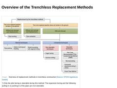
(Image: Overview of replacement methods in trenchless construction) |
|
|
|
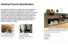
During gallery techniques or heading, the sewer or pipeline to be replaced is exposed, with the provision of a temporary protection, dismantled and replaced by a new one. The removal of the soil and the sewer or pipeline to be replaced is carried out manually with the aid of appropriate tools or machines e.g. excavators. Support arches of steel rods or special steel profiles that are placed into the gallery cross-section provide temporary support. … |

|
|
|
|
Shuttering
The term shuttering is taken from the mining area and describes the lining of the space between the individual lining elements (support arches). Steel (steel shuttering) as well as wood (wood shuttering) can be used for the shuttering process. |
|
Support arch
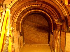
The support arches serve to reinforce the gallery. Above the support arches, at the working face, the wood or steel shuttering is pushed into the soil starting from the crown. |
|
Ventilation |
|

|
|

|
|
In the United States, there is not one single comprehensive standard that regulates the process of heading (such as in the case of Europe, for example). For example, the ASTM standard specification can be followed for sewer and manhole brick (made from clay or shale) construction [[ASTM C32-13]]. Generally, in the US, the contractor has to follow the owner's specifications for the given project. Example of European standards to be followed: |
|

|
|
|
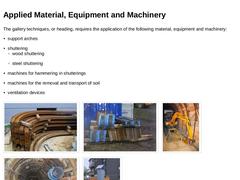
The gallery techniques, or heading, requires the application of the following material, equipment and machinery: (Image: Support arches (special steel profile) to protect the gallery) (Image: Steel shuttering) (Image: Converted mini-excavator with conveyor belt) (Image: Diffuser … |

|
|
|
This module focuses on the fundamentals of the trenchless replacement of gas, water, wastewater pipelines using the gallery techniques known from the mining industry. In addition, the individual steps of the gallery heading process with steel and timber support are described - from the preparatory measures to the final work. In addition, the areas of application and limitations of gallery heading, the measures for quality assurance as well as the advantages and disadvantages of this method are presented. After completing this module, you will have a sound knowledge of: - characteristics of gallery heading;
- working steps of this form of heading;
- relevant aspects for quality assurance.
|

|
This lecture deals with the different procedure steps of gallery techniques (heading) with steel and wood shuttering, from preparation to finished work. |