
|
|
|
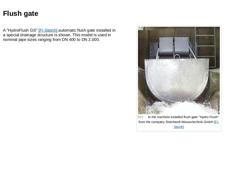
A "HydroFlush GS" [FI-Steinh] automatic flush gate installed in a special drainage structure is shown. This model is used in nominal pipe sizes ranging from DN 400 to DN 2,000.
(Image: In the manhole installed flush gate "Hydro Flush" from the company Steinhardt Wassertechnik GmbH) |
|
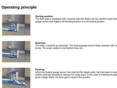
(Image: Automatic flush gate (without auxiliary energy) - Starting position) Starting position
The flush gate is equipped with a special seal that blocks the dry weather water flow. The floating gauge sensor that triggers the flushing process is in the lowest position. (Image: Automatic flush gate (without auxiliary energy) - Retention) Retention
The water is backed up upstream. The floating gauge sensor floats upwards with rising water levels. The … |
|
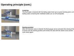
(Image: Automatic flush gate (without auxiliary energy) - Lowering) Lowering
The flush gate is lowered with the falling water level up to a given locking point, so that the trailing water containing the mobilised solids can run off unimpeded. (Image: Automatic flush gate (without auxiliary energy) - Starting position) Starting position
After the retention area is drained, the float gauge sensor activates the closing of the flush gate. It moves into the … |

|
|
|
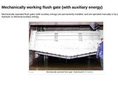
Mechanically operated flush gates (with auxiliary energy) are permanently installed, and are operated manually or by pneumatic, hydraulic or electrical auxiliary energy. (Image: Mechanically operated flush gate “HydroGuard”) |
|
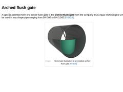
A special patented form of a sewer flush gate is the arched flush gate from the company SGS Aqua Technologies GmbH, which can be used in any shape pipe ranging from DN 300 to DN 3,000 [FI-SGS]. (Image: Schematic illustration of an installed arched flush gate) |
|
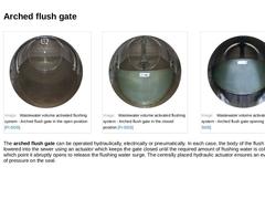
(Image: Wastewater volume activated flushing system - Arched flush gate in the open position) (Image: Wastewater volume activated flushing system - Arched flush gate in the closed position) (Image: Wastewater volume activated flushing system - Arched flush gate opening phase) The arched flush gate can be operated hydraulically, electrically or pneumatically. In each case, the body of the flush gate is lowered into the sewer using an actuator which keeps … |

|
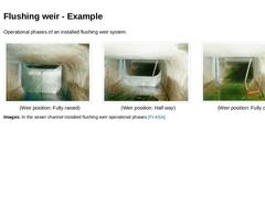
A flushing weir is a permanently installed, sealing device, consisting of a vertically movable weir plate running on rails. Flushing weirs are used for control purposes and also for the cleaning (permanent surge flushing) of large sewers, either as an individual element or as part of a system of cascading weirs. The figure shows a flushing weir application, where a 8.2 km long sewer line with nominal sizes of DN 1,200 to DN 2,400 is maintained using … |
|
Operational phases of an installed flushing weir system. (Image: In the sewer channel installed flushing weir - Fully raised position) (Weir position: Fully raised) (Image: In the sewer channel installed flushing weir - Half way position) (Weir position: Half way) (Image: In the sewer channel installed flushing weir - Fully open position) (Weir position: Fully open) Images: In the sewer channel installed flushing weir operational phases [FI-ASA]. |
|
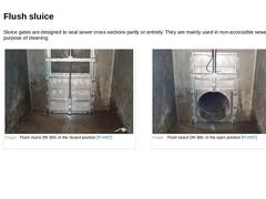
Sluice gates are designed to seal sewer cross sections partly or entirely. They are mainly used in non-accessible sewers for the sole purpose of cleaning. (Image: Flush sluice DN 900, in the closed position) (Image: Flush sluice DN 900, in the open position) |
|
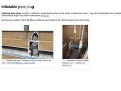
Inflatable pipe plugs provide a method of surge flushing that can be easily installed and used. They can be installed in the manhole shaft without major structural modifications [FI-HST]. During a dry weather spell, the plug is rolled up and stored in the manhole above the sewer flow. (Image: Inflatable pipe plugs - designed to back up sewer flows at low water levels) (Image: Wastewater volume activated flushing system - Inflatable pipe plug) |
|
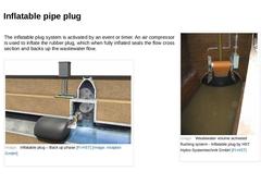
The inflatable plug system is activated by an event or timer. An air compressor is used to inflate the rubber plug, which when fully inflated seals the flow cross section and backs up the wastewater flow. | (Image: Wastewater volume activated flushing system - Inflatable plug by HST Hydro-Systemtechnik GmbH) | | (Image: Inflatable plug – Back up phase) |
|
|
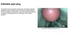
To produce the characteristic surge wave, the plug is abruptly deflated through a cylinder valve. The hose is entirely bled of air by the backed up wastewater. After the flushing procedure is completed, the flushing hose is rolled back into its initial position. (Video: Automatically inflatable pipe plug) |

|
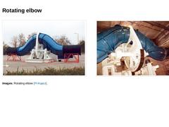
Another further development in the field of surge flushing is the rotating elbow, which has not yet found a wide demand in the industry [FI-Kasap]. Video: Rotating elbow [FI-Kasap] [Image: visaplan GmbH]. This interactive object is only visible online. |
|
Images: Rotating elbow [FI-Kupcz]. |
|
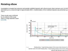
Investigations revealed that extensive and partially solidified deposits with critical erosion shear stresses up to 14 N/m2 could be eliminated up to a channel length of approximately 300 m. Sedimentation of the mobilised deposits was prevented up to a length of 700 m. These results were confirmed by an analysis of the surge wave in a large diameter sewer [Lützn96]. (Image: Rotating elbow - Surge flushing analysis of the erosion shear stresses in a … |

|
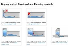
The following surge flushing methods will now be presented in more detail: -
Tipping bucket
-
Pivoting drum
-
Flushing manhole
|
|
|
(Image: Surge flushing methods - Tipping bucket) |
(Image: Surge flushing methods - Pivoting drum) |
|
|
(Image: Surge flushing methods - Vacuum operated flushing chamber) |
(Image: Surge flushing methods - Flushing chamber with flush gate) |
(Image: Surge flushing methods - Flushing manhole) |
|
|
|
|
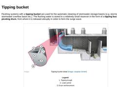
Flushing systems with a tipping bucket are used for the automatic cleaning of stormwater storage basins (e.g. stormwater sewer, stormwater overflow basin etc.). The flushing water is stored in a relatively small reservoir in the form of a tipping bucket or pivoting drum, from where it is released abruptly in order to form the surge wave. (Image: Tipping bucket detail) |
|
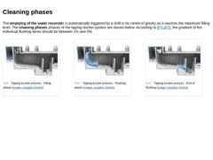
The emptying of the water reservoir is automatically triggered by a shift in its centre of gravity as it reaches the maximum filling level. The cleaning phases phases of the tipping bucket system are shown below. According to [FI-UFT], the gradient of the individual flushing lanes should be between 1% and 5%. (Image: Tipping bucket process - Filling phase) (Image: Tipping bucket process - Flushing phase) (Image: Tipping bucket process - End of flushing) |
|
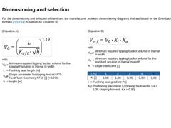
For the dimensioning and selection of the drum, the manufacturer provides dimensioning diagrams that are based on the Brombach formula [FI-UFTa] (Equation A / Equation B). (Equation A) (Formula: Spülkippe - Bemessung und Auswahl A) with: |
V0 |
= |
Minimum required tipping bucket volume for the standard solution in l/serial m width |
|
L |
= |
Flushing lane length [m] |
|
Kuft |
= |
Shape parameter for tipping bucket UFT-FluidFlush Geometry FF10 [-] (=0.071) |
|
h |
= |
|

|
The shape parameter that was also introduced by Brombach has to be empirically checked and determined for the individual drum shapes by each manufacturer. An example for such a diagram with a flushing lane gradient of 2 % is shown. (Image: Design diagram for the dimensioning of a tipping bucket with a flushing lane gradient of 2 %) |

|
|