|
Flushing systems using a flushing chamber serve to clean stormwater sewers and stormwater tanks. The flushing chamber is a specially designed structure capable of storing stormwater during flood events and back up flushing during cleaning operations. Depending on the type of the sealing device, a distinction is made between the: |
|
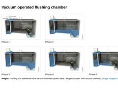
(Image: Flushing chamber schematic - initial stage (Biogest-System)) Phase 1 (Image: Retention phase of a vacuum stormwater tank system (Biogest-System)) Phase 2 (Image: Retention phase of a vacuum stormwater tank system (Biogest-System)) Phase 3 (Image: Retention phase of a vacuum stormwater tank system (Biogest-System)) Phase 4 (Image: Flushing chamber schematic - release of the flushing water) Phase 5 Images: Flushing of a stormwater tank vacuum chamber … |
|
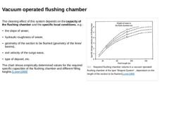
The cleaning effect of this system depends on the capacity of the flushing chamber and the specific local conditions, e.g.: -
the slope of sewer,
-
hydraulic roughness of sewer,
-
geometry of the section to be flushed (geometry of the lines/basins),
-
exit velocity of the surge wave,
-
type of deposit, etc.
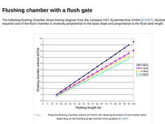
The chart shows empirically determined values for the required specific capacities of the flushing chamber and different filling heights [Loren1998] |
|
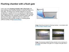
In the case of the flushing chamber with a flush gate, the lower opening of the flushing chamber is closed by means of a flush gate. The filling of the chamber depends on how the sewage flow is guided and can, for example, be implemented by arranging a restrictor or via check flap gates in the chamber walls. Depending on the operation mode the system type, the opening of the gate is triggered either by a water level measurement (with auxiliary energy) … |
|
The following flushing chamber dimensioning diagram from the company HST-Systemtechnik GmbH [FI-HST], illustrates that the required size of the flush chamber is inversely proportional to the base slope and proportional to the flush lane length.
(Image: Required flushing chamber volume [m³/m] for the cleaning procedure of stormwater tanks depending on the flushing length and the invert gradient) |

|
|
|
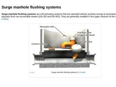
Surge manhole flushing systems are self-activating systems that are operated without auxiliary energy to automatically and regularly flush non-accessible sewers (DN 200 and DN 400). They are generally installed in the upper sections of the sewer line [FI-Funke]. (Image: Surge manhole flushing systems) |
|
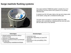
The surge manhole "FABEKUN system" consists of a 1.0 m high precast concrete section that is placed on an ordinary manhole base. It contains two DN 150 water inlets at the top and a large outlet at the bottom, along with a ventilation/overflow pipe.
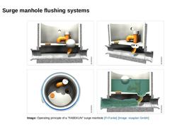
The flush valve is located in a chamber bellow the outlet opening, and is activated by a floating ball that rises and sinks with the water level in the manhole. |
|
|
(Image: Surge manhole "FABEKUN" - Empty) |
(Image: Operating principle of a surge manhole) |
|
(Image: Surge manhole "FABEKUN" - Top view) |
(Image: Surge manhole "FABEKUN" - Full) |
|
Image: Operating principle of a "FABEKUN" surge manhole [FI-Funke] [Image: visaplan GmbH] |
|

|
|
|
|

|
Surge flushing is the oldest sewer system cleaning method and is once again in demand as a result of new developments in sensor technology and telecontrol engineering. Preferred areas of use include stormwater retention tanks and storage channels. |

|
Compared to conventional high pressure cleaning, surge flushing is economically preferable, if the following conditions are present [Dohma2002a]: -
complicated access for both cleaning vehicles and staff,
-
extensive safeguards with respect to traffic control prior to high pressure cleaning,
-
need for short cleaning intervals (e.g. monthly),
-
very large deposit quantities,
-
predominantly loose, unconsolidated deposits,
-
long cleaning distances,
-
frail …
|
|
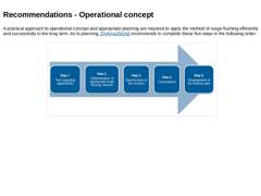
A practical approach to operational concept and appropriate planning are required to apply the method of surge flushing efficiently and successfully in the long term. As to planning, [Dohma2002a] recommends to complete these five steps in the following order: (Image: Flushing methods - Operational concept) |
|
In step 1 the applicability of surge flushing is tested in relation to the local circumstances as well as the structural, hydraulic and material limiting conditions in the sewer. |
|
In step 2, the appropriate surge flushing devices are determined considering their specific fields of application, and the requirements that are defined by the limiting conditions (step 1).
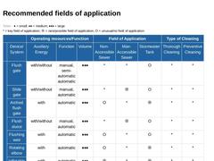
The following table includes recommendations regarding the selection of surge flushing methods depending on the operating resources/function, fields of application and type of cleaning. They are categorized into man-accessible and non-accessible sewers (< DN 800). |
|
(Table: Recommended fields of application and characteristics for surge flushing devices in accordance with [Dettm2005a]) |
|
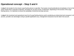
In step 3, the location for the chosen surge flushing device is specified. The location should preferably be immediately in front of the sewer section that is exposed to deposits, and allows for an easy access. Furthermore, depending on the function of the surge flushing device, it is important to ensure the availability of electrical and data services.
In step 4, the investment and operational costs for all surge flushing devices worth considering … |
|
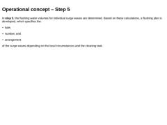
In step 5, the flushing water volumes for individual surge waves are determined. Based on these calculations, a flushing plan is developed, which specifies the: -
type,
-
number, and
-
arrangement
of the surge waves depending on the local circumstances and the cleaning task. |
|
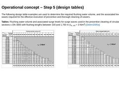
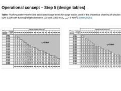
The following design table examples are used to determine the required flushing water volume, and the associated levels of surge waves required for the effective execution of preventive and thorough cleaning of sewers. Tables: Flushing water volume and associated surge levels for surge waves used in the preventive cleaning of circular cross sections ≤ DN 3000 with flushing lengths between 100 and 1,700 m (τe, crit = 3 N/m2) [Dettm2005a] |
|
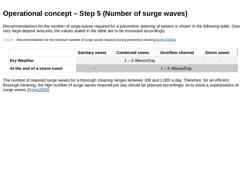
Table: Flushing water volume and associated surge levels for surge waves used in the preventive cleaning of circular cross sections ≤DN 3,000 with flushing lengths between 100 and 1,000 m (τe, crit = 5 N/m2) [Dettm2005a] (Image: Flushing water volume and associated surge levels for surge waves used in the preventive cleaning of circular cross sections ≤ DN 3,000 with flushing lengths between 100 and 1,000 m (τe, crit = 5 N/m2)) |
|
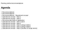
Recommendations for the number of surge waves required for a preventive cleaning of sewers is shown in the following table. Given very large deposit amounts, the values stated in the table are to be increased accordingly. (Table: Recommendations for the minimum number of surge waves required during preventive cleaning) The number of required surge waves for a thorough cleaning ranges between 100 and 1,000 a day. Therefore, for an efficient thorough … |
|
|

|
Based on the results of large-scale tests performed on storm water sewers (DN 2,500 to DN 3,400) the following conclusions, according to [Dettm2005], were drawn: -
In the case of thorough cleaning, stormwater sewers have to be designed for a critical erosion shear stress according to Shields of τe,crit = 11.9 N/m2. Here, a continuous flushing with a maximum number of surge waves per day is recommended. The surge waves should have a height of hsurge…
|
|
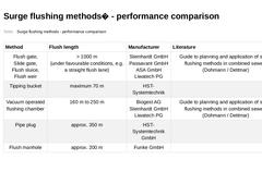
(Table: Surge flushing methods - performance comparison) |