
|
The following guidelines can be references for pipe extraction: In addition, the following European standards can also serve as a good guideline for pipe extraction process: |

|
|
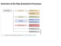
|
(Image: Overview over pipe extraction processes) |

|
|
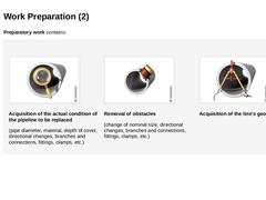
Preparatory work contains: |
|
(Image: Question) |
(Image: Question) |
(Image: Question) |
|
|
Preparatory work contains: (Image: Inspection) Acquisition of the actual condition of the pipeline to be replaced (pipe diameter, material, depth of cover, directional changes, branches and connections, fittings, clamps, etc.) (Image: Laterals) Removal of obstacles (change of nominal size, directional changes, branches and connections, fittings, clamps, etc.) (Image: Planning) Acquisition of the line's geometry |
|
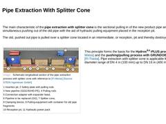
The main characteristic of the pipe extraction with splitter cone is the sectional pulling in of the new product pipe and the simultaneous pushing out of the old pipe with the aid of hydraulic pulling equipment placed in the reception pit. The old, pushed out pipe is pulled over a splitter cone located in an intermediate, or reception, pit and thereby destroyed. (Image: Schematic longitudinal section of the pipe extraction process with splitter cone … |
|
|
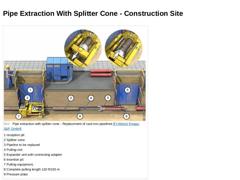
(Image: Pipe extraction with splitter cone - Replacement of cast iron pipelines [FI-Weiss]) |
|
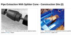
(Image: Pipe extraction for the replacement of cast iron pipelines (Hydros System) [FI-Klug] - Adapter) (Image: Pipe extraction for the replacement of cast iron pipelines (Hydros System) [ATVA127a] - Splitter cone) |

|
Preparation work for pipe extraction with splitter cone consists of the following working steps: -
Excavation and preparation of insertion and reception pits along with any required intermediate pits near house connections, as well as the removal of the pipe to be replaced out of all the pits.
-
Installing the pipe guide rail into the insertion pit.
-
Inserting the pulling rods from the reception pit into the pipeline to be replaced. Once it has reached …
|
|

|
|
(Image: Attention!) If the pipe sections to be replaced are significantly long, the installation of intermediate pits for the pipe extraction is possible and due to the skin friction quite reasonable. |
|
Intermediate pits are installed: -
in the vicinity of connection pipes (service connections, as well as drains and sewers),
-
in order to subdivide the complete pulling section into shorter, technically controllable sections (about 30 to 50 ft (10 to …
|
|
|
If an intermediate pit is installed, a splitter cone and a container for pipe fragments are integrated. The segmental pipe sections are continually pulled by the pulling equipment in the reception pit over the splitter cone, placed in the particular intermediate pit, and destroyed one after the other. (Video: Pipe extraction process Hydros®-PLUS with reference to [FI-Weiss]) Video: Pipe extraction process Hydros®-PLUS with reference to [FI-Weiss] [Image: … |
|
|
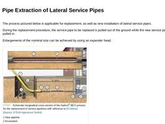
The process pictured below is applicable for replacement, as well as new installation of lateral service pipes. During the replacement procedure, the service pipe to be replaced is pulled out of the ground while the new service pipe is pulled in. Enlargements of the nominal size can be achieved by using an expander head. (Image: Schematic longitudinal cross section of the Hydros®-BOY process for the replacement of service pipelines with reference to [… |
|
|
|
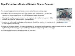
(Image: Hydros®-BOY process - Pulling-equipment positioned in the basement [FI-Weiss]) The process for pipe extraction of laterals consists of the following working steps: -
Installation of an insertion pit near the supply pipeline. The installation of a pit within the range of the house connection, or the intermediate pit, may be necessary.
-
Placing of the pulling equipment based on site requirements in either the basement of the house to be connected, …
|
|
|
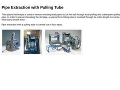
This special technique is used to remove existing lead pipes out of the soil through axial pulling and subsequent pulling in of a casing pipe. In order to prevent breaking the old pipe, a special form-fitting tube is inserted through its entire length to evenly distribute the necessary tensile force. Pipe extraction with a pulling tube is carried out in four steps. (Image: Hydros®-LEAD process for the replacement of service pipelines made of lead - … |
|
|
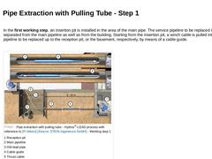
In the first working step, an insertion pit is installed in the area of the main pipe. The service pipeline to be replaced is separated from the main pipeline as well as from the building. Starting from the insertion pit, a winch cable is pulled into the pipeline to be replaced up to the reception pit, or the basement, respectively, by means of a cable guide. (Image: Pipe extraction with pulling tube - Hydros®-LEAD process with reference to [FI-Weiss] - … |
|
|
|
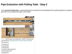
In the second working step, a special pulling tube connected to the hydraulically driven pulling equipment is pulled into the pipe that is to be replaced through a winch cable. (Image: Pipe extraction with pulling tube - Hydros®-LEAD process with reference to [FI-Weiss] [Image: S&P GmbH] - Working step 2) |
|
|
|
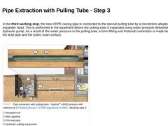
In the third working step, the new HDPE casing pipe is connected to the special pulling tube by a connection adapter with an expander head. This is performed in the basement before the pulling tube is expanded using water pressure delivered by a hydraulic pump. As a result of the water pressure in the pulling tube, a form-fitting and frictional connection is made between the lead pipe and the tubes' outer surface. (Image: Pipe extraction with pulling … |
|
|
|
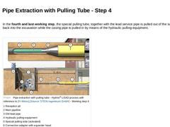
In the fourth and last working step, the special pulling tube, together with the lead service pipe is pulled out of the subsoil back into the excavation while the casing pipe is pulled in by means of the hydraulic pulling-equipment. (Image: Pipe extraction with pulling tube - Hydros®-LEAD process with reference to [FI-Weiss] - Working step 4) |
|
|
|
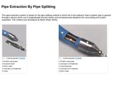
This pipe extraction system is based on the pipe splitting method in which the to be replaced, lead or plastic pipe is passed through a device which cuts it longitudinally into two halves and simultaneously displaces the surrounding soil (cutter/expander). This method was developed by Berlin Water Works. |
|
(Image: Cutter/expander [FI-BWB]) |
(Image: Cutter/expander [FI-BWB]) |
|
|
|
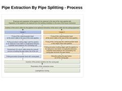
In general, there are two option for application of the pipe extraction process based on pipe splitting. With both versions, the pipe to be replaced must first be separated from the main pipeline as well as from the buildings' plumbing system. A reception pit is excavated in the area of the main line where the to be replaced pipe is additionally exposed. |
|
(Image: Attention!) Buildings with no basements need to have an additional pit excavated in … |
|
|
(Image: Pipe extraction based on pipe splitting - Working steps) |
|
|
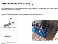
The cable winch equipment shown in the photo is used for the replacement of lead and plastic pipes as part of the pipe extraction process based on pipe splitting.
The pulling equipment is designed for a one man operation and a tensile force of 30 kN. |
|
(Image: Grundopull process - Pulling-equipment [FI-Tracta]) |
|
(Image: Grundopull process - Cutter [FI-Tracta]) |
|
(Image: Grundopull process - Turning boom [FI-Tracta]) |
|
|
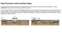
The pipe extraction with auxiliary pipes is a modification of the pipe extraction method based on pipe splitting. It is a non-destructive technique for the removal of pipes from the subsoil. In the first step, the pipe to be replaced is pressed out of the subsoil by means of recoverable, pressure-resistant steel pipes (so-called "casings"). For this purpose, the pushing and pulling equipment is installed in the reception pit, which presses the casings … |
|
|
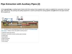
In the second step, a pulling head is fixed at the first casing in the reception pit in order to establish the connection to the new pipe. Afterwards, the pushing and pulling equipment is used to pull back the casing pipeline and pull in the new pipe towards the reception pit. (Image: Procedure for pushing/pulling process with reference to [FI-Bohrt] [Image: S&P GmbH] - Pulling in of the new pipeline (working step 2)) |
|
|
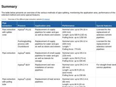
The table below presents an overview of the various methods of pipe splitting, mentioning the application area, performance of the selected method and some special features. (Table: Overview of the different pipe extraction variants) |