
|
The essential differences of the optimised installation method in comparison to the traditional way of sewer installation by use of the open trench are: -
The use of special optimised concrete pipes
-
No necessary working space at the sides of the pipe
-
The use of a special linear type of lining
-
The installation and connection of the pipes by means of a special installation system
-
The backfilling of the embedment areas between the pipe and the in …
|
|
Criteria to be taken into account with regard to pipe design: -
Prevention of installation-related damages
-
Simplified requirements for the installation of piping
-
Suitability for automated installation
-
Optimisation of the structural characteristics
-
Beneficial interrelation between pipe weight and load bearing capacity
|
|
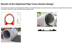
The result of the research and development efforts is the optimised pipe cross section for the nominal size range DN 20 in (500 mm) to DN 48 in (1200 mm), with a special reverse sealing collar. (Image: Optimisation of the pipe shape by means of FEM analyses) (Image: Optimised pipe) (Image: Optimised pipe with reverse sealing gasket) (Image: Detailed view: Cross section of the reverse sealing element) |
|
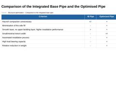
(Table: Structural optimisation – Comparison to the integrated base pipe) |

|
Reduction of the excavated quantity of soil (Image: Comparison of the traditional and the optimised installation method) (Image: Optimised installation: About 75% less excavated soil owing to a small trench) As the working space is no longer required, the trench width can be significantly reduced. Compared to the “traditional” open cut method of construction, a considerably smaller quantity of soil has to be excavated (for DN 28 in (700 mm) about 25%), … |
|
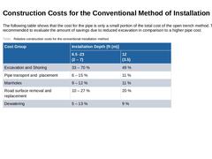
The following table shows that the cost for the pipe is only a small portion of the total cost of the open trench method. Therefore, it is recommended to evaluate the amount of savings due to reduced excavation in comparison to a higher pipe cost. (Table: Relative construction costs for the conventional installation method) |
|
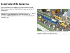
(Image: Construction site equipment in case of the “optimised method of installation”) The equipment required at the construction site is not entirely different compared to that of a "traditional" open cut method of construction. Special characteristics are the modified linear shoring, the special installation system and the technology used for both the production of the flowable fill and (where required) treatment of the excavated soil. |
|
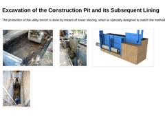
The protection of the utility trench is done by means of linear shoring, which is specially designed to match the method of installation. (Image: Initial excavation for the optimised method of installation) (Image: Insertion of the outer panels for the optimised method of installation) (Image: Insertion of the panel soldiers and outer panels for the optimised method of installation) (Image: Re-positioning of the panel soldiers (U-boogie car) for the … |
|
|
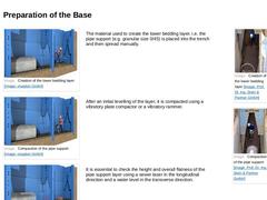
(Image: Creation of the lower bedding layer) |
The material used to create the lower bedding layer, i.e. the pipe support (e.g. granular size 0/45) is placed into the trench and then spread manually. |
(Image: Creation of the lower bedding layer) (Image: Compaction of the pipe support) |
|
(Image: Compaction of the pipe support) |
After an initial levelling of the layer, it is compacted using a vibratory plate compactor or a vibratory tamper. |
|
(Image: … |
|
|
|
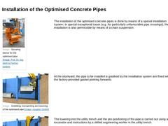
(Image: Securing device for the optimised pipe) |
The installation of the optimised concrete pipes is done by means of an excavator mounted pipe installation system. In special exceptional cases (e.g. for particularly unfavourable pipe crossings), the installation is also permissible by means of a chain suspension. |
(Image: Grabbing, transporting and lowering of the optimised pipe) |
At the stockyard, the pipe to be installed is grabbed by the installation … |
|
|
|
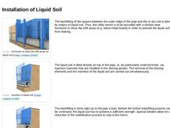
(Image: Formwork to close the infill areas for flowable fill) |
The backfilling of the spaces between the outer edge of the pipe and the in situ soil is done by means of flowable fill. Thus, the utility trench is to be provided with a section-wise formwork to close the infill areas (e.g. sheet metal board) in order to prevent the flowable fill from leaking. |
|
(Image: Insertion of flowable fill) |
The flowable fill is filled directly on top of the pipe, … |
|
|
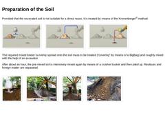
Provided that the excavated soil is not suitable for a direct reuse, it is treated by means of the Kronenberger® method: (Image: Dosing of the mixed binder) (Image: Pre-mixing and mixing by means of a crusher bucket) (Image: Separation of residues and foreign matter) The required mixed binder is evenly spread onto the soil mass to be treated (“covering” by means of a BigBag) and roughly mixed with the help of an excavator mounted mixing unit and/or … |
|
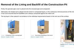
Firstly, the granular pipe cover is placed onto the encased pipe and compacted. Afterwards, the treated soil is placed into the trench in compacted layers. In the continuous removal process of the shoring elements it has to be ensured that the backfilled soil is always compacted against the native soil. The top layer is then placed in accordance to the individual requirements based on the end use of the surface. |
(Image: Compaction of the covering layer) |
|
|
|
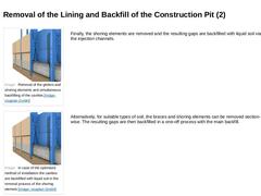
(Image: Removal of the girders and shoring elements and simultaneous backfilling of the cavities) |
Finally, the shoring elements are removed and the resulting gaps are backfilled with flowable fill via the injection channels. |
|
(Image: In case of the optimised method of installation the cavities are backfilled with liquid soil in the removal process of the shoring elemets) |
Alternatively, for suitable types of soil, the braces and shoring elements … |
|

|
-
Avoidance of the typical installation errors through the optimisation of the pipe shape, as well as the implementation of a partly automated installation method.
-
Lower quantity of excavated soil as a result of a smaller trench width
-
Lower volume of waste material to be dumped on landfill sites as the excavated material is reused
Conclusion: The optimised method of installation represents a more efficient, more environmentally sound, and less damage-… |

|
|

|
|
|
A compaction test (i.e. of the soil-mechanical parameters of the material that has been backfilled into the embedment, and used in the main backfill) is required in order to verify the load assumptions that have been made in the planning stage, or to adjust them based on changing conditions and thus, to assert that the soil-mechanical parameters of the piping comply with the requirements that have been determined in structural calculations. Furthermore, … |

|
A compaction test of the bedding layer is of particular importance, as this layer has to bear loads before the side fill, cover and main backfill are placed and compacted. Thus, a compaction test at an earlier point in time is highly recommended over a compaction test after the completion of the construction works. This ensures that subsequent settlings or subsidence can be minimised or even prevented. |

|
In order to prevent gross defects or deficiencies in the construction work and contractual debates on the evaluation of results obtained by means of different test methods and testing devices, it should be proceeded as follows (provided that nothing else is specified in the contract): |

|
-
If an agreement on the check test results cannot be achieved, direct test methods should be used for the compaction test.
-
If, due to the characteristics of the different types of soil, the test methodology of direct methods is either too difficult or too time-consuming, or if direct test methods cannot be carried to the required extent due to the progress of the construction work, indirect test methods based on either verifiable rules of thumb …
|
|
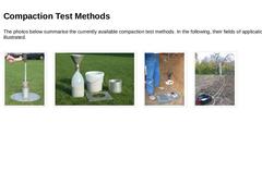
The photos below summarise the currently available compaction test methods. In the following, their fields of application will be illustrated. (Image: Core Cutter Method) (Image: Replacement Test) (Image: Dynamic Plate Load Test) (Image: Dynamic Probing) |
|
|
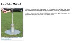
(Image: Core Cutter Method) |
The core cutter method is only suitable for fine types of soil (clays and silts) without any noteworthy coarse particle percentages as well as for (fine to medium) sands. The core cutter method is particularly suitable for cohesive types of soil with a firm consistency and medium-densely packed fine sands. |
|
|
|
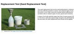
(Image: Replacement Test) |
The sand replacement test can be used productively in cohesive and non-uniformly grained or coarse, non-cohesive types of soil, into which a core cutter cannot be inserted without affecting the soil fabric (fine to medium types of sand, gravel-sand mixtures). In types of soil with particles larger than that of coarse gravel (2-5 in / 63 mm) or with pore spaces large enough to be penetrated by the test sand, the sand replacement … |
|
|
|
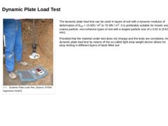
(Image: Dynamic Plate Load Test) |
The dynamic plate load test can be used in layers of soil with a dynamic modulus of deformation of EVd = 15 MN / m2 to 70 MN / m2. It is preferably suitable for mixed- and coarse particle, non-cohesive types of soil with a largest particle size of ≤ 0.02 in (0.63 mm). Provided that the material under test does not change and the tests are correlative, the dynamic plate load test by means of the so-called light drop … |
|