|
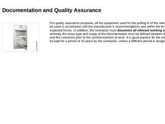
For quality assurance purposes, all the equipment used for the pulling-in of the new pipeline is to be used in accordance with the manufacturer’s recommendations and within the limits of the expected forces. In addition, the contractor must document all relevant working steps, whereby the exact type and scope of the documentation must be defined between the owner and the contractor prior to the commencement of work. It is good … |
|
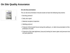
On-site Documentation The on-site documentation should include at least the following documents: -
Bursting protocol
-
Daily site report
-
Material reception inspection
-
Welding protocol
-
Protocol of the tensile forces during the pulling-in, or rather documentation of the overload protection (if used)
-
Protocols of the leak-tightness (vacuum) testing for sewer pipes and pressure testing for water and gas pipelines
|
|
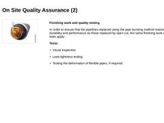
(Image: Leaktightness) Finishing work and quality testing In order to ensure that the pipelines replaced using the pipe bursting method maintain the same durability and performance as those replaced by open cut, the same finishing work and quality tests apply: Tests: |
|
|
|
Congratulations! You have successfully finished this module. Next you will have the opportunity to review the newly acquired knowledge with an interactive questionnaire. You can navigate back to any point in the modules if you wish to review a specific point or subject. Stay curious! |
|
Replacement of supply and disposal pipelines (gas, water, wastewater) means the construction of new pipelines in the same alignment, whereby the new installations incorporate the function of the original pipeline.
This module covers the pipe bursting replacement technique associated with the trenchless construction method.
After completing this module, you will have a sound knowledge of:
- rules and regulations;
- pipe bursting methods, their areas and limits of application and their advantages and disadvantages;
- selection of suitable pipe bursting methods depending on pipe defects and boundary conditions.
|
|
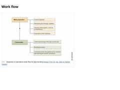
(Image: Sequence of operations work flow for pipe bursting) |
|
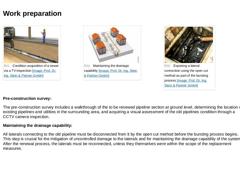
(Image: Condition acquisition of a sewer via a TV-inspection) (Image: Maintaining the drainage capability) (Image: Exposing a lateral connection using the open cut method as part of the bursting process) Pre-construction survey: The pre-construction survey includes a walkthrough of the to be renewed pipeline section at ground level, determining the location of existing pipelines and utilities in the surrounding area, and acquiring a visual assessment … |
|
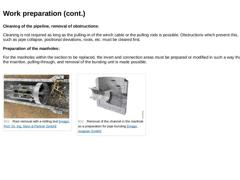
Cleaning of the pipeline, removal of obstructions: Cleaning is not required as long as the pulling-in of the winch cable or the pulling rods is possible. Obstructions which prevent this, such as pipe collapse, positional deviations, roots, etc. must be cleared first. Preparation of the manholes: For the manholes within the section to be replaced, the invert and connection areas must be prepared or modified in such a way that the insertion, pulling-through, … |
|
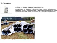
Inspection and storage of the pipes on the construction site: Upon arrival at the site, the pipes are to be inspected for faults. In addition, the delivery papers are also to be checked in order to ensure that all of the information corresponds with the original order details. These checks are to be documented as part of the quality assurance procedure. (Image: HD-PE discrete long pipes DA 500) |
|
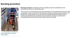
(Image: Bursting head with a directional guide) Bursting procedure: Introduction of the new pipeline under the consideration of the permissible tensile forces and bending radii. There must be an overlap between the external diameter of the expander head and that of the new pipeline in order to reduce the frictional forces during the pulling through procedure. The tensile forces acting directly on the new pipeline during the bursting procedure must … |

|
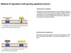
(Image: Realisation of pipe bursting from the insertion manhole to the reception manhole) Manhole to manhole: Utilization of discrete pipes and bursting equipment suited to the size of the manhole structure. (Image: Realisation of pipe bursting from the insertion manhole to the reception pit) Manhole to pit: Utilization of discrete pipes and bursting equipment suited to the size of the manhole structure. Installation of the pulling equipment in the pit. |
|
(Image: Realisation of pipe bursting from the insertion pit to the reception manhole) Insertion pit to manhole: Installation of the pulling equipment in the manhole or above it. The discrete pipes or the continuous pipeline, together with the bursting unit, is inserted through the insertion pit. The size of the bursting unit is accordingly dimensioned as to allow for its removal from the target manhole. (Image: Realisation of pipe bursting from insertion … |
|
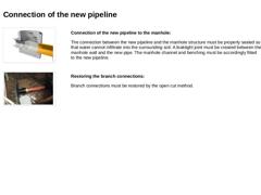
(Image: Connection of the new pipeline to the manhole) Connection of the new pipeline to the manhole: The connection between the new pipeline and the manhole structure must be properly sealed so that water cannot infiltrate into the surrounding soil. A leaktight joint must be created between the manhole wall and the new pipe. The manhole channel and benching must be accordingly fitted to the new pipeline. (Image: Re-connection of a lateral to the new … |

|
|

|
|
|
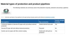
(Image: Gravity pipeline) The following materials are commonly used in the production of gravity, protection and product, pipelines: (Table: Commonly used types of new pipelines for the pipe bursting of gravity systems with reference to [DWAM143-15]) |

|
Other pipe types include: (Table: Other types of new pipelines qualified for the pipe bursting of gravity systems with reference to [DWAM143-15]) |

|
(Image: Gravity pipeline) If polyethylene pipes are to be used, only PE 100 or PE-Xa pipes specified by the DVGW Worksheet (GW 335-A3 and GW 335-A2) should be considered. |
Material |
Pipe joint |
External protection |
|
PE 100 |
Connection using a heated butt joint and removal of the weld bead |
External protection is necessary and is to be restored in the weld area. |
|
PE-Xa |
None, only use with coiled pipes, because the welding of PE-Xa is only possible with … |
|
|
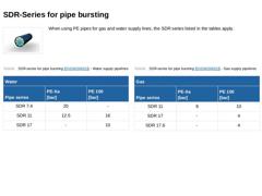
(Image: Rohricon) When using PE pipes for gas and water supply lines, the SDR series listed in the tables apply. (Table: SDR-series for pipe bursting - Water supply pipelines) (Table: SDR-series for pipe bursting - Gas supply pipelines) |
|
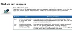
(Image: Rohricon) Steel and cast iron pipes
Steel pipes used for gas pipelines need to be in accordance with DIN EN 10208-1 and DIN 2470-1. For steel pipes used as water pipelines DIN 2460 applies, and for cast iron water pipelines DIN EN 545 applies. |
Material |
Joint |
External protection |
|
Steel |
Welded joints according to DVGW work sheet GW 350 |
External protection is required (e.g. cement mortar coating or glass fiber reinforced synthetic resin … |
|
|
|
|
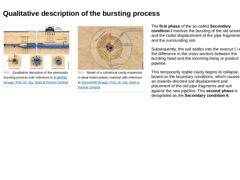
(Image: Qualitative decription of the pneumatic bursting process with reference to [Falk95b] [Image: S&P GmbH]) (Image: Model of a cylindrical cavity expansion in ideal elasto-plastic material with reference to [Zimme88] [Image: S&P GmbH]) The first phase of the so-called Secondary condition I involves the bursting of the old sewer and the radial displacement of the pipe fragments and the surrounding soil. Subsequently, the soil settles into the overcut ( … |
|
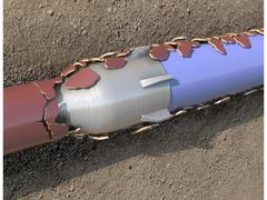
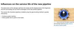
(Image: Groove and notch formation caused by pipe breakage fragments) The destruction of the old pipe wall from the inside and the displacement of its fragments into the surrounding soil can lead to damages to the new product pipeline. The service life of product pipelines installed using the pipe bursting method is greatly reduced by : -
Grooves and/or notches,
-
Stress peaks due to point or line loads.
|

|
Grooves and notches can occur in all pipe materials. According to DVGW, grooves of up to 10 % of the wall thickness are permissible for pressure pipelines. Plastic pipes are especially prone to grooving because of their material properties. (Table: Characteristics of the E-modulus (short term and long term) for various materials) |