|
|
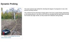
(Image: Dynamic Probing) |
The most common test method for checking the degree of compaction in situ is the dynamic probing method. This method has the advantage of being able to test even at great depths (depending on the testing device in use up to 130 ft (40 m)), provided that the back-filled soil does not include any larger stones, as they would form obstacles during testing. |
|
|
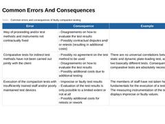
(Table: Common errors and consequences of faulty compaction testing) |
|
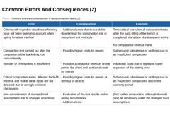
(Table: Common errors and consequences of faulty compaction testing (2)) |
|
|

|
Congratulations! You have successfully finished this module. Next, you will have the opportunity to review the newly acquired knowledge with an interactive questionnaire. You can, of course, still navigate back to any point in the modules if you wish to review a specific topic or subject. Stay curious! |

|
The installation of water and wastewater networks is carried out around the world to a large extent in open cut construction. This module focuses on all of the relevant information relating installation and alignment of the pipes, backfill compaction, alternative backfill materials, and the removal of the shoring. Upon the successful completion of this module, you will be able to: - identify and apply the main rules and regulations,
- ensure a high quality of workmanship on site,
- identify and assess construction errors, and
- optimise the installation process.
|
|
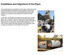
The transportation and positioning of the pipes within the trench should principally be performed using equipment specifically designed for this task. When moving particularly heavy pipe sections, the equipment operating limits should be strictly followed. In principle, only equipment adapted to the pipe (such as pipe grabs, etc.) should be used for transporting and lowering the pipes into the trench. Large concrete pipes usually have built-in lifting … |

|
Connection of the individual pipe segments must be performed according to the manufacturer's specifications. In addition: -
When joining the pipes, suitable devices are to be used.
-
The pipe section being installed is to be suspended freely during the joint connection, pushing or sliding the pipe on the prepared bedding is to be especially avoided with heavy pipes.
-
If the pipes are not connected manually, only devices which allow for a controlled …
|
|
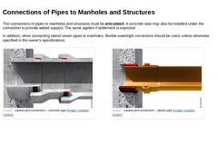
The connections of pipes to manholes and structures must be articulated. A concrete seat may also be installed under the connection to provide added support. The same applies if settlement is expected. In addition, when connecting lateral sewer pipes to manholes, flexible watertight connectors should be used, unless otherwise specified in the owner's specifications. (Image: Lateral joint connection – concrete pipe) (Image: Lateral joint connection – … |
|
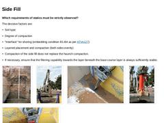
Which requirements of statics must be strictly observed? The decisive factors are: -
Soil type
-
Degree of compaction
-
"Interface" for shoring (embedding condition B1-B4 as per [ATVA127])
-
Layered placement and compaction (both sides evenly)
-
Compaction of the side fill does not replace the haunch compaction.
-
If necessary, ensure that the filtering capability towards the bedding layer beneath is always sufficiently stable.
(Image: Bedding compaction … |
|
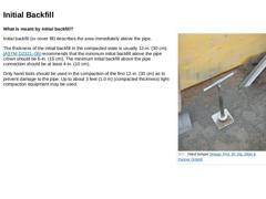
(Image: Hand tamper) What is meant by initial backfill? Initial backfill (or cover fill) describes the area immediately above the pipe. The thickness of the initial backfill in the compacted state is usually 12-in. (30 cm). [[ASTM D2321–05]] recommends that the minimum initial backfill above the pipe crown should be 6-in. (15 cm). The minimum initial backfill above the pipe connection should be at least 4-in. (10 cm). Only hand tools should be used in … |
|
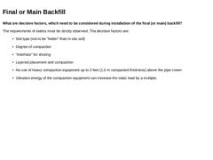
What are decisive factors, which need to be considered during installation of the final (or main) backfill? The requirements of statics must be strictly observed. The decisive factors are: -
Soil type (not to be "better" than in situ soil)
-
Degree of compaction
-
"Interface" for shoring
-
Layered placement and compaction
-
No use of heavy compaction equipment up to 3 feet (1.0 m compacted thickness) above the pipe crown
-
Vibration energy of the compaction …
|

|
The backfill of the embedment differs between four conditions [ATVA127]: (Table: Cover Filling Conditions A1-A4 as per ATV-DVWK-A 127) |
|
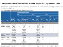
The table below provides information about soil compaction, layer thickness, and number of passes, depending on the heaviness of the compaction equipment. (Table: Soil compaction, layer thickness, and number of passes [DWAA139]) (Table: Soil Classification (DWA-A 139)) |
|
|
|
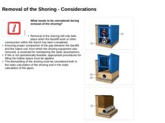
(Image: Attention!) What needs to be considered during removal of the shoring? -
Removal of the shoring will only take place when the backfill work or other construction within the trench has been completed.
-
Ensuring proper compaction of the gap between the backfill and the native soil, from which the shoring equipment was removed, is essential for maintaining the static assumptions.
-
If this is not operationally feasible, appropriate procedures for …
|

|
What needs to be considered during removal of the shoring? -
The structural analysis specifications must be strictly observed (embedding and backfill condition as per [ATVA127]
-
The choice of another shoring method may require a static recalculation.
-
When using sheet piles which extend below the trench base, computations as per [ATVA127] are not sufficient.
|
|
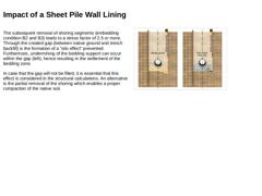
The subsequent removal of shoring segments (embedding condition B2 and B3) leads to a stress factor of 2.5 or more. Through the created gap (between native ground and trench backfill) is the formation of a “silo effect" prevented. Furthermore, undermining of the bedding support can occur within the gap (left), hence resulting in the settlement of the bedding zone. In case that the gap will not be filled, it is essential that this effect is considered … |
|
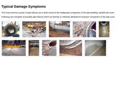
The most common causes of pipe failures are a direct result of the inadequate compaction of the pipe bedding, backfill and cover. Following are examples of possible pipe failures which are directly or indirectly attributed to improper compaction of the pipe zone. (Image: Longitudinal failure) (Image: Inappropriate use of a heavy compactor) (Image: Failure to meet the minimum trench width) (Image: Failure to meet the minimum trench width) (Image: Inadequately … |
|
|
|
|

|
Flowable fill is a self-compacting low strength material with a flowable consistency that is used as an economical fill or backfill material, as an alternative to compacted granular fill. Flowable fill is not concrete nor it is used to replace concrete. Terminology used by [[ACI 229R]] for this material are unshrinkable fill, controlled density fill, flowable mortar or lean-mix backfill. On the following pages are presented the advantages and disadvantages … |
|
Hydraulically bounded filling materials consist principally of the following raw materials: -
Filler material, such as native aggregates or recycled materials
-
Plasticizer, for example, mixture of water swellable clay (bentonite), foaming agents, air pore-forming additives (surfactants) or other mineral, organic and / or inorganic additives,
-
Stabilizer (binder), such as cement or lime.
The hydraulically bonded fill mixture is composed of about 95% … |
|
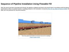
After the trench has been excavated and shored, the pipeline is alligned and fixed to the trench base in accordance with the planning specifications either on wooden boards or sandbags (based on the calculation concept by [Prof. Dr.-Ing. Stein & Partner GmbH], the latter are to be preferred for structural reasons). (Image: Pipe string aligned and bedded on the trench base and on sandbags) |
|
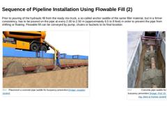
Prior to pouring of the hydraulic fill from the ready mix truck, a so-called anchor saddle of the same filler material, but in a firmer consistency, has to be poured on the pipe at every 2.00 to 2.50 m (approximately 6.5 to 8 feet) in order to prevent the pipe from shifting or floating. Flowable fill can be conveyed by pump, chutes or buckets to its final location. |
(Image: Placement a concrete pipe saddle for buoyancy prevention) |
(Image: Concrete … |
|