|
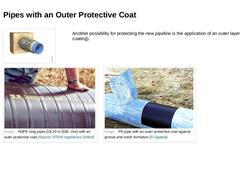
(Image: Application of pipes with an outer protective coat) Another possibility for protecting the new pipeline is the application of an outer layer (protective coating). (Image: HDPE long pipes DA 20 in with an outer protective coat) (Image: PE-pipe with an outer protective coat against groove and notch formation [FI-Egepla]) |
|
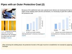
(Image: Peeling off the protective coat of an Egeplast Saftey-Line coated pipe (SLM) [FI-Egepla]) (Image: Preparing the welding seam (left: removing the welding bead, right: bandaging the welded seam with a GRP bandage) [FI-Egepla]) Because of the additional outer coat, special cover sleeves are necessary for butt welding. In the region of the welding seam and the connections, it is necessary to peel off a sufficient width of the protective coat. |
|
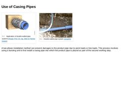
(Image: Application of double-walled pipe systems) (Image: Double-walled pipe system [Jürge05]) A two-phase installation method can prevent damages to the product pipe due to point loads or line loads. This process involves using a bursting unit to first install a casing pipe into which the product pipe is placed as part of the second working step. |
|
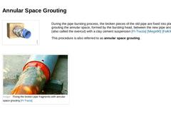
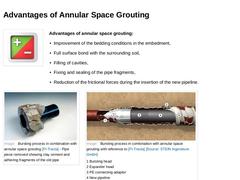
(Image: Lubrication of the new pipeline and fixing of the pipe fragments of the replaced pipe with a clay cement suspension) During the pipe bursting process, the broken pieces of the old pipe are fixed into place by grouting the annular space, formed by the bursting head, between the new pipe and the cavity (also called the overcut) with a clay cement suspension [FI-Tracta] [Miege90] [Falk95b]. This procedure is also referred to as annular space grouting |
|
(Image: Plus/Minus Icon) Advantages of annular space grouting: -
Improvement of the bedding conditions in the embedment,
-
Full surface bond with the surrounding soil,
-
Filling of cavities,
-
Fixing and sealing of the pipe fragments,
-
Reduction of the frictional forces during the insertion of the new pipeline.
(Image: Bursting process in combination with annular space grouting - Pipe piece removed showing clay cement and adhering fragments of the old … |

|
|

|
1st Factor
Tip: Pipe material (Image: Fragezeichen) 2nd Factor
Tip: Soil condition (Image: Fragezeichen) 3rd Factor
Tip: Bursting unit (Image: Fragezeichen) You will find the correct answer on the following page. |
|
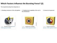
The required bursting force depends on: 1. Breaking resistance of the old pipeline 2. Displacement capability of the soil in the embedment (Image: Breaking resistance) (Image: Displacement capability) (Image: Amount of expansion) |
|
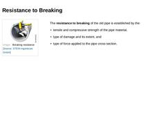
(Image: Breaking resistance) The resistance to breaking of the old pipe is established by the: -
tensile and compressive strength of the pipe material,
-
type of damage and its extent, and
-
type of force applied to the pipe cross-section.
. |
|
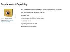
(Image: Displacement capability) The soil displacement capability is mostly established by its density. The main influencing factors include the: -
type of soil,
-
density and consistency of the layers,
-
depth of cover,
-
primary stress level, and
-
stress and strain history.
|
|
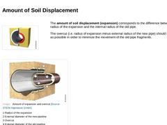
(Image: Amount of expansion) The amount of soil displacement (expansion) corresponds to the difference between the radius of the expansion and the internal radius of the old pipe. The overcut (i.e. radius of expansion minus external radius of the new pipe) should be as small as possible in order to minimize the movement of the old pipe fragments. (Image: Amount of expansion and overcut) |
|
In determining the amount of soil displacement, the following questions must be answered while taking into account the existing soil conditions: In order to prevent surface heaving or settling, a minimum depth of cover of 10 times the amount of expansion has proven to be effective. … |
|
A buffer between parallel pipes of at least three times the amount of expansion (minimum 40 cm) has proven to be effective for cohesive soils [DWAM143-15:2005] Here is an example for the calculation of expansion amounts in cohesive soils: Diameter of the old pipeline: DN 10 in (250 mm)
Diameter of the new pipeline: DN 11 in (280 mm)
External diameter of the expansion: DN 13 in (340 mm) Calculation according to DWA-M 143-15: 3 x ( … |
|
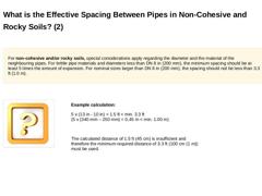
For non-cohesive and/or rocky soils, special considerations apply regarding the diameter and the material of neighbouring pipes. For brittle pipe materials and diameters smaller than DN 8 in (200 mm), the minimum spacing should be at least 5 times the amount of expansion. For nominal sizes larger than DN 8 in (200 mm), the spacing should not be less than 3.3 ft (1.0 m). Here is an example for the calculation of expansion amounts … |
|
For non-cohesive and/or rocky soils, special considerations apply regarding the diameter and the material of the neighbouring pipes. For brittle pipe materials and diameters less than DN 8 in (200 mm), the minimum spacing should be at least 5 times the amount of expansion. For nominal sizes larger than DN 8 in (200 mm), the spacing should not be less than 3.3 ft (1.0 m). Example calculation: 5 x (13 in - 10 in) = 1.5 ft < min. … |
|
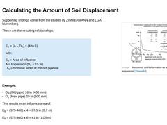
(Image: Measured soil deformation as a result of an expansion [Zimme88]) Supporting findings come from the studies by ZIMMERMANN and LGA Nuremberg. These are the resulting relationships: Eb = (A – DN) x (4 to 6) with: Eb = Area of influence
A = Expansion (De + 15 %)
DN = Nominal width of the old pipeline Example: -
DN (Old pipe) 16 in (400 mm)
-
De (New pipe) 20 in (500 mm)
This results in an influence area of: Eb = (575-400) x 4 = 27.5 in (0,7 m) Eb = (575-… |
|
|

|
|
|
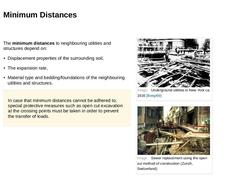
The minimum distances to neighbouring utilities and structures depend on: -
Displacement properties of the surrounding soil,
-
The expansion rate,
-
Material type and bedding/foundations of the neighbouring utilities and structures.
In case that minimum distances cannot be adhered to, special protective measures such as open cut excavation at the crossing points must be taken in order to prevent the transfer of loads. (Image: Underground utilities in … |
|
Soil deformation is generally defined as the horizontal or vertical positional change of the soil surface or a point inside the soil. Vertical soil deformation in the direction of the ground surface is called heaving and in the opposite direction is referred to as subsidence, settling or settlement. |
|
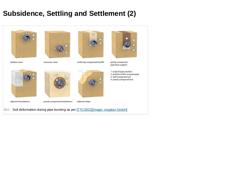
Subsidence is the vertical displacement of an entire soil layer (stratum), as a result of soil movement at a great depth. In this case, the size of the displacement can be determined, but not its timing [Schmi96]. Settling occurs in granular soils due to a sudden rearrangement of the grain particles caused by the addition of water. For loosely compacted soils, this settling can amount to up to 5 % of the layer thickness, and for densely compacted … |
|
(Image: Soil deformation during pipe bursting as per [TTC2001]) |
|
|
|
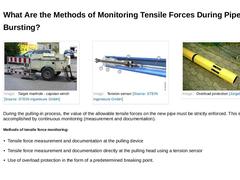
(Image: Target manhole - capstan winch) (Image: Overload protection [Jürge05]) During the pulling-in process, the value of the allowable tensile forces on the new pipe must be strictly enforced. This is accomplished by continuous monitoring (measurement and documentation). Methods of tensile force monitoring: |
|
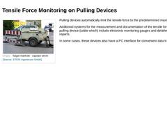
(Image: Target manhole - capstan winch) Pulling devices automatically limit the tensile force to the predetermined maximum value. Additional systems for the measurement and documentation of the tensile forces on the pulling device (cable winch) include electronic monitoring gauges and detailed printout reports. In some cases, these devices also have a PC interface for convenient data transfer. |