
|

| (Image: Attention!)
For reasons of economy, locally limited damage is repaired. Repeated and extensive damage at the same place in which a repair is no longer possible can be rehabilitated either by renovation or by replacement. If hydraulic overloading or a reduction in cross section caused by renovation measures cannot be accepted, then only replacement comes into question. | Locally limited
damage (Image: Locally limited damage)
| Repeated and
extensive … |
|

|
| (Image: Decision process for the selection of structural solutions with reference to DIN EN 752-5 [DINEN752-5b])
|
|

|
Repair | | (Image: Parts of section)
| (Image: Discrete pipes)
| (Image: Pipe joints)
| (Image: Branch connections)
| Renovation | | (Image: At least one section)
| | | | Replacement | | (Image: At least one section)
| | | |
|

|
|
Depending on the type of rehabilitation within the trenchless method, the existing substance of the old pipeline is fully used, partially used or not used at all. | Repair (Image: Repair)
Full or partial use of the original substance of the old pipeline | Renovation (Image: Renovation)
Full or partial use of the original substance of the old pipeline | Replacement (Image: Replacement)
No use of the original substance of the old pipeline |
|

|
|
Depending on the structural condition of the rehabilitation section, the rehabilitated pipeline must take on the following loads: - groundwater load
- soil load
- traffic load
- dead load of construction
| |
(Image: Loading of the rehabilitated pipeline - Groundwater load)
|
(Image: Loading of the rehabilitated pipeline - Traffic load)
|
(Image: Loading of the rehabilitated pipeline - Soil load)
|
(Image: Loading of the rehabilitated pipeline - Dead load of … |
|
|

|
|

|
This lecture is part of the series "Trenchless 101" and serves to provide an overview of rehabilitation of gas, water and wastewater pipelines. |

|
This lecture is part of the series "Trenchless 101" and serves to provide an overview of trenchless renovation methods for supply and disposal lines. Special emphasis is placed on the lining processes of pipes. The coating processes are not part of this lecture. |
|
|
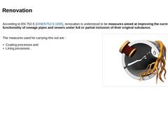
According to EN 752-5 [DINEN752-5:1995], renovation is understood to be measures aimed at improving the current functionality of sewage pipes and sewers under full or partial inclusion of their original substance. | |
The measures used for carrying this out are : - Coating processes and
- Lining processes .
| (Image: Damages)
|
|
|
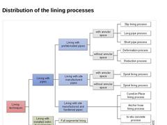
| (Image: Distribution of the lining processes)
|
|

|
|
|
|
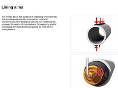
Full linings serve the purpose of replacing or enhancing the resistance properties to physical, chemical, biochemical and/or biological attacks, for hindering the renewed formation of incrustations, for replacing and/or increasing the static bearing capacity as well as the leaktightness. | |
(Image: Structural calculation)
|
|
(Image: Leaktightness)
|
|
|
|
|
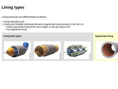
Lining processes are differentiated as follows - lining with pipes and
- Lining with installed individual elements (segmental lining process) in the form of
- Partial segmental lining of the invert region or the gas space and
- Full segmental lining
| Lining with pipes |
(Image: Lining with prefabricated pipes)
|
(Image: Lining with site manufactured pipes)
|
(Image: Lining with site manufactured and hardened pipes)
|
| Segmental lining (Image: Segmental lining)
|
|
|
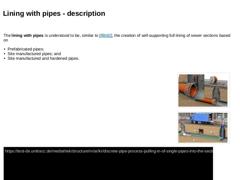
The lining with pipes is understood to be, similar to (not found), the creation of self-supporting full lining of sewer sections based on -
Prefabricated pipes;
-
Site manufactured pipes; and
-
Site manufactured and hardened pipes.
|
|
|
|
(Image: Depiction of the lining with site manufactured pipes (spiral lining process) using the RIB-LOC-Relining-System as an example with reference to [FI-RIBLOb] - Sketch of principle [Image: S&P GmbH]) |
|
(Image: Insertion … |
|
|
|
|
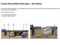
Lining with prefabricated pipes is characterised by the pulling, pushing or driving-in of pipes (also lining pipes) into the section of the sewer to be rehabilitated. One differentiates between: - Lining with continuous pipes
- Lining with discrete pipes
|
(Image: Conventional sliplining process with annular space with reference to [FI-Teerb] - Depiction of principle [Image: S&P GmbH])
|
(Image: Discrete pipe method - Pulling-in of discrete pipes into the … |
|
|
|
|
(Image: PVC-profile PVC HI type 1 - cross section)
|
|
(Image: Winding of pipe)
|
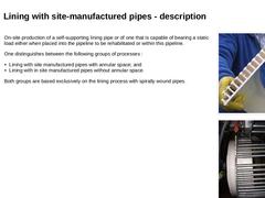
On-site production of a self-supporting lining pipe or of one that is capable of bearing a static load either when placed into the pipeline to be rehabilitated or within this pipeline. One distinguishes between the following groups of processes : - Lining with site manufactured pipes with annular space; and
- Lining with in site manufactured pipes without annular space.
Both … |
|
|
| (Image: Insertion of the liner hose by means as an example with the Insituform process)
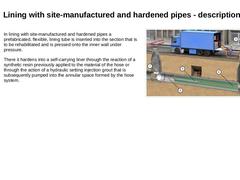
In lining with site-manufactured and hardened pipes a prefabricated, flexible, lining tube is inserted into the section that is to be rehabilitated and is pressed onto the inner wall under pressure. There it hardens into a self-carrying liner through the reaction of a synthetic resin previously applied to the material of the hose or through the action of a hydraulic … |
|
|
|
|
|
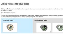
Pulling-in a flexible and butt-welded continuous plastic pipe via an excavation or a manhole into the section to be rehabilitated by means of a winch. One differentiates between: - Lining with continuous pipes with annular space (The annular space between lining pipe and inner sewer wall is grouted)
- Lining with continuous pipes without annular space (Lining with close-fit pipes)
| with annular space (Image: Principle depiction of the annular space grouting)
|
|
|
|
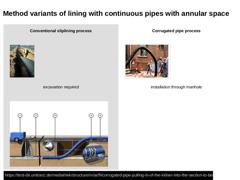
Conventional sliplining process (Image: Conventional sliplining process with annular space [FI-Teerb] - View of the pulling-in excavation with continuous pipe)
excavation required (Image: Conventional sliplining process with annular space with reference to [FI-Teerb] - Depiction of principle [Image: S&P GmbH]) |
Corrugated pipe process (Image: Corrugated pipe process - Inserting the corrugated pipe into the entry manhole (Baypren) [FI-Phoena])
installation … |
|
|
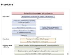
| (Image: Sequence diagram for the lining with continuous pipes with annular space)
|
|
|
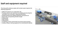
| (Image: Equipment for lining with prefabricated pipes with anular space)
The lining with continuous pipes with annular space requires the following equipment: - Staff of 4-6 persons on construction site
- Possibly devices and machines for installing and securing the excavation (e.g. excavator, supporting elements)
- Heating element butt welding equipment and power set
- Winch with corresponding tensile strength
- Pulling head
- Roller blocks
- Lifting device
- Compulsory …
|
|
|
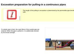
| (Image: Attention!)
The length of the pulling-in excavation is determined by the permissible pipe bending radii. | |
If a plastic pipe is bent, the outer fibres of the outside pipe are strained. When the pipe is pulled-in, it is additionally strained by the tensile strength. | (Image: Loads of outer fibres of the continuous pipe when pulled in)
|
|

|
|
|
|
(Image: Principle depiction of the annular space grouting) |
The annular space formed by the insertion of the lining pipe is grouted in order to achieve, among others, the following (not found): -
Fixing the liner;
-
Avoiding the entrance of soil and water;
-
Creating a defined bedding in the sewer;
-
Even transfer of external loads;
-
Prevention of dangerous gas bubbles.
Further advantages of grouting the annular space are: -
Preventing the collapse …
|
|
|
|
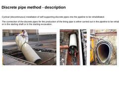
Cyclical (discontinuous) installation of self-supporting discrete pipes into the pipeline to be rehabilitated. The connection of the discrete pipes for the production of the lining pipe is either carried out in the pipeline to be rehabilitated or in the starting shaft or in the starting excavation. |
(Image: Installation of a GRP-discrete pipe into the starting excavation)
|
(Image: Taking-up and driving -in of the GRP pipes: step 2)
|
(Image: Driving-… |
|
|
